Monday, October 9, 2023

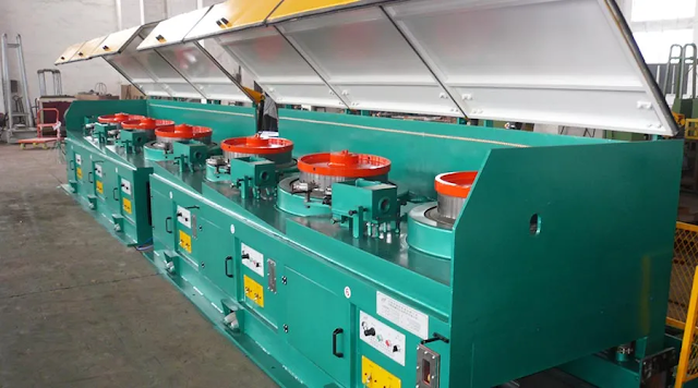
Variable-frequency Drive Wire Drawing Machine Application

Wire Drawing Machine


Variable-frequency Drive Wire Drawing Machine Application

1. Device Overview

The high-speed wire drawing machine is mainly used for drawing copper wire. Its main electrical transmission part consists of a drafting motor, a take-up motor, and a wire arrangement motor. 

Other auxiliary parts of the equipment include a swing bar (tension frame), positioning wheel, line dividing wheel, reciprocating wire arrangement rod, etc. 

The drafting motor drives the drawing wheel to operate. The four-stage drawing wheel is linked through the belt to realize metal stretching, and the take-up motor realizes winding. 

The equipment overview and functional requirements are as follows:

1.1 Basic parameters of equipment:

Product name: High speed thin wire drawing machine

Drafting motor (KW): 11/4P

Take-up motor (KW): 4/4P

Incoming wire diameter (mm): Φ0.6-1.20

Outlet wire diameter (mm): Φ0.08-0.32

Maximum mechanical speed (m/s): 2500(max)

Tension frame resistance value: 5KΩ

1.2 Technical specifications and requirements:

◎ Synchronization requirements when the equipment starts to increase speed;

◎ Keep the tension constant when the equipment is running;

◎ Synchronization is required when parking, without wire breakage or tension relaxation;

◎ Disconnection protection required for equipment safety production;

◎ Inching threading function

◎ External button starts operation;

◎ Running speed display;

◎ The diameter ratio of the winding empty disk to the full disk is about 1:3;

◎ Full plate weight is about 50kg;

◎The maximum operating frequency is about 70HZ.

2. System composition

◎ According to the equipment conditions, select the following models and components as electrical transmission equipment

INV1: Drafting VFD (Variable-frequency Drive) Sunwoele HSF600

INV2: Winding VFD (Variable-frequency Drive) Sunwoele HFV3000

Braking resistor: 1000W/80Ω

◎ The drafting motor adopts Sunwoele HSF600 VFD (Variable-frequency Drive), and the winding motor adopts HFV3000 winding-specific VFD (Variable-frequency Drive) (with external braking resistor)

The operation command and output frequency signal of the host INV1 is used as the operation command and frequency command of the slave INV2 to achieve synchronous operation.

◎ When parking, brake in the opposite direction for a heavy disc to prevent wire breakage caused by inertia.

◎ Use the JOG function to realize the jogging function during threading operations

◎ The pendulum output voltage signal is used as the feedback signal for internal variable PID correction control, and VFD (Variable-frequency Drive) unique winding curve is used for speed prediction graphic operation to achieve constant linear speed winding to meet process requirements.

◎ The pendulum output voltage signal is used as the feedback signal for internal variable PID correction control, and VFD (Variable-frequency Drive) unique winding curve is used for speed prediction graphic operation to achieve constant linear speed winding to meet process requirements.

3. Conclusion

During the entire working process of the high-speed thin wire drawing machine, the process requirements are mainly to maintain constant tension during winding. 

Especially during high-speed operation and rewinding, there are higher requirements for the acceleration and deceleration synchronization control of VFD (Variable-frequency Drive) and the control of the inertia of the rewinding wheel during deceleration and parking. 

After debugging and running, series VFD (Variable-frequency Drive) meets the user's process requirements during acceleration and deceleration operation, high-speed operation, and parking braking.

In order to meet the requirements for safe production, the disconnection protection function of the series VFD (Variable-frequency Drive), in addition to the normal set correction amount holding area, the winding VFD (Variable-frequency Drive) uses the frequency value given by INV1 As a reference value, the PID adjustment effect caused by the action of the tension frame is limited.

Tuesday, July 18, 2023

What is Enameled Wire?

Enameled Wire


What is Enameled Wire?


Enameled wire, also known as wound wire or coil insulated wire, is an insulating material widely used in the manufacture of electrical products. It must meet the requirements of various uses and manufacturing processes. These requirements include the shape and size of the enameled wire, and its ability to work at high temperatures for short and long periods of time. On some special occasions, the enameled wire needs to be able to withstand strong vibration and centrifugal force at high speed or withstand corona and breakdown under high voltage. In addition, enameled wires need to be able to withstand chemical corrosion under special atmospheric conditions.


In addition to the above physical performance requirements, the enameled wire also needs to be able to withstand mechanical stress such as stretching, bending, and abrasion during the manufacturing process. At the same time, in the process of dipping and drying, the enameled wire also needs to be able to withstand phenomena such as expansion and erosion.


According to the basic composition of enameled wire, conductive core wire, and electrical insulation layer, enameled wire can be classified. In general, enameled wires can be classified according to the insulating material used and the method of manufacture. For example, enameled wire, wound wire, enameled wire, and inorganic insulated wire are common classifications.


The manufacturing process of enameled wire is relatively complicated. First, the corresponding lacquer liquid is applied to the conductor, then the solvent is evaporated, and the lacquer film is cured and cooled. According to the different insulating enamel used, the enameled wire can be divided into various types, such as polyester enameled wire, polyester imide enameled wire, polyamide-imide enameled wire, polyimide enameled wire, etc. Sometimes, it is also classified according to the particularity of its use, such as self-adhesive enameled wire, refrigerant-resistant enameled wire, etc.


The earliest enameled wire is oily enameled wire, which is made of tung oil and so on. However, due to the poor abrasion resistance of the paint film, this type of enameled wire cannot be directly used to manufacture motor coils and windings. Therefore, it needs to be wrapped with cotton yarn when used. Later, the advent of polyvinyl formal enameled wire greatly improved its mechanical properties, so that it can be directly used in motor windings, known as high-strength enameled wire.


With the development of weak current technology, self-adhesive enameled wire appeared. This type of enameled wire does not require dipping and baking to obtain coils with better integrity. However, due to its poor mechanical strength, it can only be used in micro motors and small motors. In addition, in order to avoid the trouble of removing the paint film when soldering, a direct soldering enameled wire has been developed. In the high-temperature tin enameled bath, the paint film can fall off by itself, making the copper wire easy to fall off and solder.


Composite enameled wire is a new type of enameled wire developed in recent years. Its inner and outer paint films are composed of different polymer materials, such as polyetherimide/polyamide-imide enameled wire.


Wednesday, June 7, 2023

The Manufacturing Process of Cemented Carbide Wire Drawing Die

Carbide Wire Drawing Die


The Manufacturing Process of Cemented Carbide Wire Drawing Die


1. Mold Blank Processing

The core of the cemented carbide wire drawing die will shrink during the sintering process, and the amount of shrinkage varies greatly due to the difference in composition, pressing, and sintering process; due to the different shrinkage rates of each part of the mold blank, it often forms a "saddle" or "trumpet" shape. 

Although the fluctuation of the shape and size of the mold blank meets the mold standard, it far exceeds the interference requirement of the mold group, which leads to serious uneven prestress of the mold core during mold loading, and greatly reduces the service life of the mold. 

Therefore, the mold blank must be ground externally, and a special fixture must be used on the grinding machine to grind it with a diamond grinding wheel.


2. Interference Amount of Installation Settings

In order to obtain a certain prestress of the mold core during installation, the diameter of the inner hole of the mold sleeve should be smaller than the outer diameter of the mold core. 

The difference between the two is called the interference amount. 

The amount of interference should be determined according to the size and deviation of the mold core, the draft stress, and the method of the sleeve. 

There are two types of mold sets: hot pressing method and cold pressing method. The cold pressing method has a small interference and a small precompression stress. 

It is mostly used to make wire drawing dies with smaller specifications and draw soft metals.


3. Mold  Sleeve Processing

The molded sleeve is formed by turning on a lathe, and the control points during processing are as follows:

(1) The roughness of the inner diameter of the mold sleeve must reach 0.80-I.6m, which is conducive to close cooperation with the mold sleeve;

(2) The inner diameter of the mold sleeve should correspond to the outer diameter of the mold blank to ensure that the interference of each mold is accurate;

(3) The bottom surface of the inner hole of the mold sleeve must be parallel to the outer end surface of the mold, and ensure that it is perpendicular to the center line of the mold hole after installation;

(4) The ellipticity of the inner hole of the mold sleeve should be as small as possible, not more than 0.02mm. When hot-loading, the outer surface of the mold sleeve should be polished and smooth to ensure uniform cooling after installation.


4. Mounting Process

The cold press mounting process involves pressing the blank into a mold sleeve with a press at room temperature. 

The cold pressing method requires accurate interference between the mold core and the sleeve, and high dimensional accuracy. The advantage is that no heating equipment is required, which saves energy and reduces costs.

Wednesday, May 17, 2023

Automatic Wire Drawing Machine Use Precautions

Automatic Wire Drawing Machine


Precautions for the Use of Automatic Wire Drawing Machine


The automatic wire drawing machine is suitable for surface drawing and sweeping treatment of copper, iron, stainless steel, etc., and is widely used in various industries such as machinery, automobiles, and hardware parts. 

In order to help you use the automatic wire drawing machine correctly, YF Metal Tech summarizes some precautions for using the automatic wire drawing machine, let’s have a look together.


1. Before operating the automatic wire drawing machine, you need to check the power supply and keep it intact. The specific process of safe start-up of the automatic wire drawing machine is to connect the external power supply first, then turn on the main power switch of the equipment, and finally start the power switch of the equipment.


2. Make sure to check the exhaust port of the body motor before work, and make sure it is unobstructed.


3. Carry out a safety inspection on the automatic wire drawing machine before work, and let the wire drawing machine run idly. In addition, it is also necessary to check whether the fasteners of each part are loose to ensure safe production.


4. During the working process of the automatic wire drawing machine, you should always check whether the impeller and the motor connecting rod are loose, which is conducive to finding problems in time, and can work after adjustment, so as to ensure the safety of personnel in production.


5. When replacing the impeller of the automatic wire drawing machine, the power should be turned off first, and after the power is replaced, check whether the equipment is normal.


6. If it is found that the automatic wire drawing machine is working abnormally, it should stop working immediately and check the equipment. If the problem cannot be solved, find a maintenance worker in time for repair.


7. It is forbidden to extend any part of your body into the polishing area when the automatic wire drawing machine is working automatically to prevent injuries.


8. When the polishing machine is working, if there is an emergency, the main power switch should be turned off immediately.


9. At the working site of the automatic wire drawing machine, it is necessary to keep the ground clean and tidy, and not to place objects randomly.


10. The motor should be maintained regularly, and the bed dust should be cleaned every Saturday, and the motor should be maintained, so as to ensure the normal operation of the wire drawing machine equipment.


11. It is not allowed to randomly connect and pull wires at random. When cleaning or cleaning the equipment, water should be prevented from splashing on the power supply.


12. Non-staff personnel should not enter the work area without authorization to avoid danger.


The above content is organized by YF Metal Tech.


YF Metal Tech focuses on the R&D and manufacturing of wire drawing machines and polishing machines. Currently, it provides automatic wire drawing machines, planar wire drawing machines, plate wire drawing machines, water mill wire drawing machines, round tube wire drawing machines, stainless steel wire drawing machines, and other equipment. Welcome to consult.


Wednesday, April 26, 2023

Straight-in Wire Drawing Machine Applicable Standards

https://yfmetaltech.com/straight-in-wire-drawing-machine-applicable-standards/


Straight-in Wire Drawing Machine Applicable Standards


The straight-in wire drawing machine is a non-sliding way to draw medium and low carbon steel wire, stainless steel wire, molded steel wire, and non-ferrous metal wire coarse and medium diameter and developed equipment, suitable for standard parts industry, supermarket shelf production industry, steel wire to material processing enterprises.


The straight-in wire drawing machine mainly comprises frame, reducer box, reel, drop wire frame, carriage, pneumatic system, communication frequency control electric control system, and motor.


The reel is placed upside down in the lower part of the reduction box, and the drawn wire can be collected directly to the drop wire frame, and then the end of the large tray collects the wire again.


The drive system of the straight-in wire drawing machine uses a powerful narrow V-belt combination hardened gear reducer or oscillating ring reducer; the wire collecting plate is serious; the reel is forced air cooled; the pneumatic pressure wheel; the lower wire plate is independently driven and the diameter of the lower wire coil is adjustable; the communication frequency conversion speed control makes the machine easy to operate, safe and reliable, and saves more than 30% of energy.


Straight into the wire drawing machine in the motor through the pulley and three-stage gear drive, driving the reel placed on the reducer box rotation output shaft, traction wire end pulling.


After pulling the wire through the lead roller, into the drop wire frame, the drop wire frame and reel synchronous rotation.


The straight-in wire drawing machine is highly automated and can draw and collect wires together.


The wire collecting plate can be as large as 2 tons, easy and reliable to unload, simple operation, high production efficiency, safe, and reliable; it can be positively rotated and decontrolled when the whole machine is running, so as to avoid the formation of accidents by mistake; the appearance is neat and beautiful.


Tuesday, April 25, 2023

What is a Metal Drawing Machine?

Metal Drawing Machine


What is a Metal Drawing Machine?


YF Metal Tech Introduces the System Components of a Wire Metal Drawing Machine

◎ The following models and components are selected as electrical transmission equipment for the wire metal drawing machine situation

INV1: Draw frequency converter S011Z3

INV2: Winding frequency converter S004G3

Braking resistor: 1000W/70Ω

S011Z3 inverter for the drawing motor and S004G3 inverter for the winding motor (with external braking resistor)

Synchronous operation by using the operation command and output frequency signal of the main machine INV1 as the operation command and frequency command of the slave machine INV2

◎ When stopping, reverse direction braking is used to prevent wire breakage caused by inertia for heavy full reels

◎ JOG function to realize the pointing function during the threading operation

◎ Internal variable PID complementary control using the pendulum output voltage signal as a feedback signal Speed prediction graphic operation with the unique winding curve of the Sanchip inverter series to achieve constant wire speed winding and meet process requirements.

◎ Internal variable PID correction control with the pendulum output voltage signal as the feedback signal, and speed prediction graph operation with the unique winding curve of inverter series, to achieve constant line speed winding and meet the process requirements.

YF Metal Tech’s main products are drying boxes, pay-off equipment, wire drawing machines, linear wire drawing machines, cleaning machines, winding machines, annealing furnaces, rewinding machines, flip-top water tank drawing machines, baling machines, and double twisting machines.

Year-round for stainless steel and carbon steel extension enterprises to undertake technical transformation and complete sets of equipment manufacturing.


Friday, March 10, 2023

What is Cast Iron?

What is Cast Iron


What is Cast Iron?


The material consists of iron with more than 2% of carbon.

Cast iron is a very wide range of consumer as well as commercial applications.


Types of Cast Iron


1. Gray Cast Iron

Most common consists of small fractures of a graphite micro-structure which is responsible for creating the appearance of a gray color.

The gray cast iron offers various compressive strengths as steel. This as a result makes it a popular choice for metal applications that can involve compressive strength.


2. White Cast Iron

It has an off-white color, which in turn results in iron compounds that are known as cementite.

White cast iron is known to be hard, so having excellent resistance against abrasions.


3. Ductile Cast Iron

Also known as nodular cast iron it is a type of soft, ductile iron alloy accompanied by a high carbon content.

Its graphite is in the form of very tiny nodules that are accompanied with the graphite in the form of concentric layers which forms the nodules.

The properties are similar to the malleable iron, whereas the parts can be cast with larger sections.


4. Malleable Cast Iron

Created by using the heat treatment processes on the white cast iron.

As a result, the carbon in iron carbide is found to transform into either graphite or ferrite plus carbon.

The slow process forms spheroidal particles instead of flakes.

The properties of malleable cast iron are likely to be those of mild steel.


5. Alloy Cast Iron

The properties of the cast iron are changed by adding various alloying elements.


Please contact stella@hanrm.com for a quotation.

And free send inquiries to us.

Email: stella@hanrm.com   stellarollingmill@gmail.com

Whatsapp/Wechat:+8615877652925


Featured Post

Bar & Wire Rod Rolling Mill Production Line Process Flow (Complete Version)

Bar & Wire Rod Rolling Mill Production Line Process Flow (Complete Version) 1. Bar Rolling Mill Production Line Process Flow  Billet acc...

Popular Articles

My Blog List

Wikipedia

Search results