Tuesday, March 29, 2022

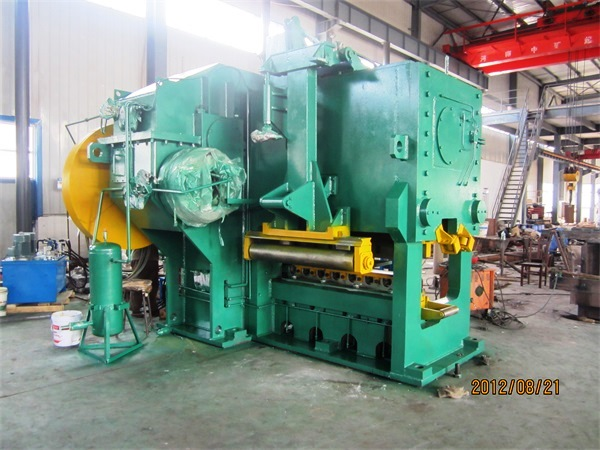
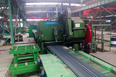
What is a Wire Rod Mill Laying Head?

Wire Rod Mill Laying Head


What is a Wire Rod Mill Laying Head?


The laying head of wire rod mill is the key equipment in high-speed wire production to spin rolled wires into coils for collection.

Wire rod mill laying head is one of the key equipment in high-speed wire production and an important bottleneck restricting further speed-up of high-speed rolling mill. The quality of wire spinning directly affects the physical quality of high-speed wire. With its special shape structure and certain speed, the laying head changes the straight current wire moving at high speed into coils with stable ring shape and uniform spacing. With the increase of wire rolling speed and output, the requirement for wire rod mill laying head is getting higher and higher. Therefore, many high-speed wire production enterprises will have unstable coils in production, which will affect product quality and smooth production.

With the development of wire production technology, horizontal wire rod mill laying head has become the throat part of the production line as a coiling equipment matching with the uncoiled cooling line. Its function is to guide the wire rolled from the finishing mill K1 or pinched in a straight line into a horizontal laying head machine. The wire slips relatively without twist in the tapping tube with rotation. Under the action of centrifugal force, Coriolis force, inertia force and friction force, it bends and deforms gradually along with the shape of the tapping tube, reaches the required curvature at the outlet, forms the spiral coil and realizes its working purpose.

The high-speed wire rod mill laying head is a horizontal structure, which is located between the water-cooled box and the cold-controlled roll track of the controlled cooling line after the finishing mill. Horizontal laying head machine is composed of transmission device, shield, tapping disc, hollow shaft, tapping tube, bearing seat, motor, bevel gear pulley and other components. The threading machine is driven by a motor and driven by a pair of bevel gears meshing in the gear box to rotate the hollow shaft. The threading tube is installed on the threading disc, which is connected with the hollow shaft by bolts. 


Hani Tech is one of the manufacturers of Long Rolling Mills and Melt Shops. We have experience from decades in design and supply of rolling mill equipment. We are catering to the requirement of Long Rolling Mills from 50000 TPY to 1 Million TPY on turnkey basis. We are able to design, manufacture, install and commission your hot rolling mill plant from A to Z. Upgrading your existing Bar and Wire Rod mills, to increase production and improve efficiency and product quality, is our specialization. Hot rolling mills, turn-key rolling mills for long products, upgrading and revamping of rolling mills, gearboxes, fully automatic rolling mill plant, design and engineering rolling process, rolling mill erection, rolling mill commissioning, re-engineering of rolling mill process, rolling mill stands, cooling beds, rolling mill supervision, TMT quenching system, and rolling mill roll pass design.

Please contact stella@hanrm.com for a quotation.
And free send inquiry to us.
Email: stella@hanrm.com   stellarollingmill@gmail.com
Whatsapp/Wechat:+8615877652925
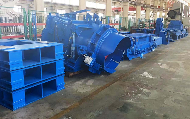
wire rod mill laying head


Wire Rod Mill


Friday, March 18, 2022

Walking Beam Cooling Bed

Walking Beam Cooling Bed

Walking Beam Cooling Bed

The walking beam cooling bed and continuous casting billet turnover cold bed series products are mainly applicable to bar, profile and billet production lines in iron and steel smelting industry. The step-by-step cold bed can meet the annual production capacity of 100-1 million tons.

The walking beam cooling bed consists of four parts, i.e. feeding system, body of the cold bed, leveling device and feeding device. The feeding system uses cylindrical roller bed to be tilted and positioned. Frequency converter roller bed motor drives independently. The feeding on roller bed is braked by a single skirt. The feeding mechanism includes curved plate type, pinch roll belt trough type and brake apron type. Brake apron lifting includes hydraulic, mechanical and other structural forms. The cold bed is step-by-step. Input roller is controlled by frequency conversion or driven directly by AC, while output roller is driven by AC.

Walking beam cooling bed is the working table for effective cooling of rolled products (threaded steel, round steel, steel pipe, etc.) in metallurgical rolling steel industry.

Classification:

 The walking beam cooling bed mainly include pull-tooth type, rack step type, pawl type, chain type and roller type.

Composition: 

The walking beam cooling bed consists of mechanical transmission system, water cooling system, working table of the cold bed, fixing support, etc.

Working principle: 

The rolled products are conveyed into the cold bed through the roller track, and then the work pieces arranged on the cold bed are moved to the top of the cold bed step by step by step by rack pulling the teeth. The cooling effect of the work pieces is achieved.

Main application: 

The walking beam cooling bed equipment is mainly used for slow natural cooling of rolled steel plate on-line. On the profile production line, the cold bed also has the function of pre-bending the profile to prevent irregular bending of the profile due to unequal quality everywhere during the natural cooling process.

Application field: 

Walking beam cooling bed is mainly used in iron and steel industry, metallurgical industry, etc.

Environment and Conditions for Equipment Use: 

Ambient Temperature: -20-+40 C

Working environment: not suitable for flammable and explosive

Altitude: +108 M


Please contact stella@hanrm.com for a quotation.
And free send inquiry to us.
Email: stella@hanrm.com   stellarollingmill@gmail.com
Whatsapp/Wechat:+8615877652925

walking beam cooling bed


Tuesday, March 15, 2022

What is a Rolling Mill?

rolling mill

What is a Rolling Mill?

The steel rolling mill is the equipment to realize the metal rolling process. Generally refers to the equipment used to complete the whole process of rolling production, including main equipment, auxiliary equipment, lifting and transportation equipment and ancillary equipment. But generally speaking, the rolling mill only refers to the main equipment.

II. Nomenclature of Rolling Mill

It is named after the type of rolled product, the type of mill and the nominal size. The principle of "nominal dimension" refers to the section mill as the pitch diameter of the herringbone gear of the gear base; the blooming mill as the nominal diameter of the roll; the strip mill as the length of the working roll body; and the steel tube mill as the maximum diameter for production. It is sometimes named after the inventor of a rolling mill (e.g. Sendzimir mill).

III. Selection of Rolling Mills

The type and dimension of finished or semi-finished rolling mill shall be selected according to the requirements of product variety, specification, quality and output, equipped with necessary auxiliary, lifting, transportation and accessory equipment, and finally balanced according to the requirements of various factors.

IV. COMPONENTS OF STEEL ROLLING MILLS

1. Work stand: composed of roll, roll bearing, frame, rail seat, roll adjustment device, upper roll balance device and roll changing device, etc.

2. Roll: It is a part that makes metal plastic deform.

3. Roll bearing: support the roll and maintain the fixed position of the roll in the frame. Roll bearings vary greatly with heavy working loads, so small coefficient of friction, sufficient strength and stiffness are required, and rolls can be easily replaced. Different types of roll bearings are used for different mills. Rolling bearings are mainly used for work rolls of strip mills because of their high rigidity and small coefficient of friction, but their small pressure-bearing capacity and large size. Sliding bearings have two types: semi-dry friction and liquid friction. Semi-dry friction roller bearings are mainly bakelite, copper and nylon bearings, which are relatively inexpensive and are mostly used in profile mills and billet openers. There are three kinds of hydrodynamic, hydrostatic and hydrostatic bearings. The advantages are small friction coefficient, large pressure-bearing capacity, high working speed and good rigidity, while the disadvantage is that the oil film thickness changes with speed. Liquid friction bearings are mostly used for support rolls in strip mills and other high-speed mills.

4. Mill stand: It is composed of two "archways" to install the roll bearing block and roll adjusting device. It needs sufficient strength and steel strength to withstand the rolling force. There are two main types of rack, closed type and open type. Closed stand is an integral frame with high strength and rigidity, mainly used for blooming mills and strip mills with high rolling force. Open frame is composed of frame body and upper cover, which is easy to change rolls. It is mainly used in cross section mills. In addition, there are no archway mills.

5. The rolling mill track base is used to install the frame and fix it on the foundation, also called the floor plate. To withstand the gravity and tipping moment of the worker base while ensuring the accuracy of the mounting dimensions of the worker base.

6. Roll adjustment device: used to adjust the roll gap so that the rolled piece can reach the required section size. Upper roll adjustment device, also known as "press-down device", has three kinds: manual, electric and hydraulic. Manual press-down devices are commonly used in profile mills and small mills. Electric press-down device includes electric motor, reducer, brake, press-down screw, press-down nut, press-down position indicator, spherical pad and pressure gauge and other components; it has low transmission efficiency, large rotating inertia of moving parts, slow reaction speed and low adjustment accuracy. Since 1970s, AGC (Automatic Thickness Control) system has been used in strip rolling mills. Hydraulic press device has been used in new strip cold, hot and thick rolling mills, which has the advantages of small thickness deviation and high product qualification.

7. Upper roll balancing device: device used for lifting upper roll and preventing impact of rolled parts when entering and leaving the roll. Forms are: spring type, multi-purpose on profile rolling mill; hammer type, commonly used on blooming mill with large roll movement; hydraulic type, multi-purpose on four-roll strip rolling mill.

In order to improve the operation rate, it is required that the roll change of the rolling mill be quick and convenient. Roll change modes are C-hook type, sleeve type, trolley type and frame type. Roll change in the first two ways is assisted by crane, while the whole frame requires two sets of frame for roll change. This method is mostly used for small mills. Car roll change is suitable for large rolling mills and facilitates automation. At present, the rapid automatic roll changing device is used on the rolling mill. It only takes 5-8 minutes to change the roll once.

8. Driving device: It consists of electric motor, reducer, gear seat and connecting shaft. The gear base distributes the drive torque to two or more rolls.

9. Auxiliary equipment includes a series of equipment for auxiliary process in rolling process. Such as raw material preparation, heating, steel turning, shearing, straightening, cooling, flaw detection, heat treatment, pickling and other equipment.


Please contact stella@hanrm.com for a quotation.
And free send inquiry to us.
Email: stella@hanrm.com   stellarollingmill@gmail.com
Whatsapp/Wechat:+8615877652925


rolling mill for sale


Sunday, March 13, 2022

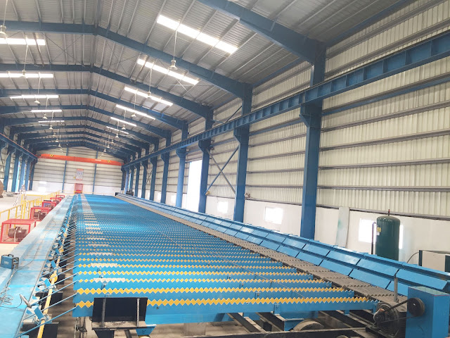
12000KN Cold Shear

Cold Shear

12000KN Cold Shear

Introduction to Cold Shear

The 12000KN cold shear is a complete set of mechanical, electrical and hydraulic integrated equipment jointly designed and manufactured by foreign parties on the basis of absorbing the technical features of international advanced shearing machines. The cold shear is suitable for shearing small bar, flat steel and other rolled products. It runs smoothly, reliably and has flat section. Each technical index and performance are not lower than that of imported similar products and has a very high cost performance ratio. At the same time, Party B can provide high-quality spare parts in time to ensure stable and reliable operation of Party A's equipment.

Bar Specifications and Steel Grades

Shear steel: 60Si2CrVAT, GCr15, 42CrMo, 60CrMoBA, 51CrV4.

Maximum shear specification: round steel φ 60. Flat steel 53x100 (50CrV4); 40x130 (40Cr).

Main Technical Parameters

Shear force: 15000KN

Shear material: σ Bmax=1865MPa

Maximum shear material specification: φ 60

Maximum number of shear elements ( φ 60): nmax=4 ( σ B=1865MPa)

Max. flat steel size: 53x100

Maximum number of sheared flat steels: 2

Shear frequency: 20 times per minute

Shear opening: 210mm

Blade length: 1400mm

Blade inclination: 2O

Tool Installation: Flat, Forming Knives

Shear temperature: normal temperature (short term 500 oC)

Roller width: 1300mm

Drive motor: 160KW; 1500r/min. AC

Hydraulic clutch brakes (including hydraulic stations) (imported from Germany)

Grease lubrication station, about 23 lubrication points

Cutting machine outline size, length x width x height (mm) 2800x6000x4500 (mm)


The 12000KN cold shearing machine mainly consists of main motor, pulley, flywheel, hydraulic clutch brake, reducer, crankshaft, cutter frame shearing device, frame body, press device, cutter changing device, hydraulic control system, lubrication system and electric control system.

12000KN Cold Shear Structure

Belt Drive

The main motor transfers motion to the flywheel via a triangular belt (the flywheel is connected to the passive pulley) with a transmission ratio of i1=2.3. At this point, the flywheel will save energy.

Hydraulic clutch, brake and reducer

The clutch closes and the flywheel transfers motion to the reducer. When the clutch is opened, the braking function will be achieved, the reducer will stop working and the flywheel will idle. Reducer speed ratio i1=30. Hydraulic clutch brake is an imported component. Hydraulic control system is manufactured in China.

Crankshaft, shearing device

The crankshaft is mounted on the frame body with an eccentricity of 105mm. The crank cutter frame is mounted on the crankshaft and the cutter frame moves up and down in the slide of the frame body. When the clutch is closed, the reducer works and drives the crankshaft to turn. The crank holder moves down rapidly from a high position to achieve shearing (the blade is mounted on the holder via the holder). After shearing, the crankshaft tool holder moves upwards with the crankshaft rotation. When moved to high position, the clutch opens and brakes immediately. At this point, the crankshaft stalls. Wait for the next cycle. Clutch opening, closing and braking are accomplished by a proximity switch controlled hydraulic system.

Frame body and frame are door frame structures of cast-welded structure

The crankshaft is mounted in a copper alloy bushing on the frame. The tool holder is mounted in the frame body slide. The runway is made of copper alloy liners and fitted on the runway. The diagonal sliding plate has the function of adjusting the clearance between the tool holder and the sliding track, and the normal clearance is 0.1mm~0.25mm. Excessive small or large clearance will affect the quality of the section.

Blade clamping and replacement device

The blade is mounted on the upper and lower tool holders, the upper tool holder is mounted on the tool holder, and the lower tool holder is mounted on the tool holder, which is compressed by several butterfly springs. Hydraulic cylinders are installed at the rear of each group of butterfly springs. The blades are replaced hydraulically. The piston of the hydraulic cylinder pushes the butterfly spring to relax the holder and release the holder from the holder. At this point, the hydraulic cylinder piston in the frame body pushes the tool holder out half way. The knife base can be lifted out by the crane. When the new tool holder is lifted into position, the piston of the hydraulic cylinder pulls it into the tool holder position. At this point, the cylinder piston on the rear seat of the butterfly spring exits. The butterfly spring compresses the base of the blade and replaces the old and new blades.

Pressing device

Press device, which is composed of press head, lever and cylinder. Its function is to fix the shear firmly so as to achieve stable shear. Its compression is achieved by an electrically controlled hydraulic system. The position of the press material can be adjusted according to the size of the shear specification and is completed by the hydraulic cylinder.

Hydraulic system

The imported hydraulic clutch brake uses the most advanced hydraulic control system in Germany. The system controls the opening, closing and braking of the hydraulic clutch.

Blade replacement, pushing out and pulling in hydraulic system utilizing existing equipment of Party A. System pressure 12 MPa.

The hydraulic control of the press device is the same as that of the clutch.

lubrication system

Lubrication system (including dry oil pump station) is grease centralized lubrication, which mainly lubricates each sliding bearing and friction pair, about 23 points. Through the grease lubrication station, grease is fed into each lubrication point through the pipe through the distributor.

Electrical control system

The electric control system consists of a control cabinet and an operating platform. The main motor uses frequency-sensitive resistor. Each control point and process control is completed by a Siemens S7-200 programmable controller. Low voltage components are Schneider products.


Please contact stella@hanrm.com for a quotation.
And free send inquiry to us.
Email: stella@hanrm.com   stellarollingmill@gmail.com
Whatsapp/Wechat:+8615877652925
Cold Shear


Thursday, March 10, 2022

Repair Technology for Bearing Position Wear of Cold Shearing Machine

cold shearing machine

Repair Technology for Bearing Position Wear of Cold Shearing Machine

Introduction of Cold Shearing Machine

Cold shearing machine is the main equipment for finishing section in bar production line. Its function is to cut the finished rolled piece to a fixed scale. Its structure (see Figure 1) consists of: cutting edge, crankshaft, pulley, electric motor, brake and clutch. The flywheel is mounted on the main shaft, and the motor drives the flywheel to run through the belt. During the shearing action, the clutch connects the main shaft to the flywheel, so that the reducer drives the eccentric wheel to run, and the shearing frame equipped with cutting edges completes the shearing action downwards.

Reasons for Wear of Cold Shear Shaft

In a bar workshop of an iron and steel enterprise, the cold shearing machine suffers from wear problems. The wear location is the mating surface between pulley and spindle. The diameter of the spindle is 180mm and the wear width is 110mm. The damage location is local deep wear, the maximum wear is about 5mm, and the bearing type is SKF2236EC.

Generally, there are many reasons for wear of shaft type. All kinds of defects during manufacture and bad problems in different stages of assembly, maintenance and use during use may cause wear of bearing position. Apart from these problems, the principal reason is that the metal properties used to fabricate shafts are determined by their high hardness, but poor concessionality (which cannot be restored after deformation), poor impact resistance and poor fatigue resistance, which easily lead to adhesive wear, abrasive wear, fatigue wear, fretting wear, etc. Most of the shaft wear problems are not easy to detect. Only when high temperature, large runout, abnormal noise and other conditions occur, most of the shafts have been worn seriously, resulting in machine shutdown.

Repair Process of Cold Shear Shaft

The traditional method to deal with this kind of bearing position wear problem is to transport the shaft to the machine repair plant after disassembly for repair welding and bushing insertion, etc. However, the process of repair welding machine itself is easy to cause local thermal stress on the shaft surface and cause hidden danger of shaft breakage. Moreover, the process of repair welding machine needs a lot of manpower and time to dismantle, transport and install the equipment. The repair time is long and the comprehensive repair cost is high. The cold shearing machine is shut down by accident and must restore the operation of equipment quickly and effectively. Therefore, traditional repair technology is obviously not suitable for this repair of bearing position wear.

Polymer composites can select different repair processes according to the parameters such as rotational speed of equipment, bearing type and service requirements. After observing the field conditions, it is found that a large area of datum surface still exists. Only partial damaged parts can be filled and repaired by materials. Components of the Fossil Blue process can be used to repair the relationship (see Figure 2), which has the characteristics of short repair time, high repair accuracy, low repair cost, no secondary damage to the equipment and easy operation.

Implementation Process of Site Plan

1. Surface treatment: First, bake the worn position to remove the grease which penetrates into the metal micropore;

2. Grinding: Use sandpaper to grind the worn area and clean it with alcohol or acetone.

3. Harmonizing Material: Harmonizing Fossil Blue Proportionally ® 2211F material and stir evenly until there is no color difference.

4. Coating material: Use 2211F material to fill out the wear position and slightly exceed the wear amount.

5. The inner race of the bearing is assembled directly after being dried with mould release agent, and the bearing can be started up after material curing is completed.

Through years of application experience in industrial field, after unexpected sudden shutdown caused by wear of driving parts in enterprises, the technology can make corresponding repair plans according to the operating conditions and design parameters of different equipment and the forming characteristics of polymer composites. It can solve the problem of wear on the transmission part of equipment in the first time, and meet the operation conditions of most equipment to the maximum extent by using the limited basic conditions in the field, thus greatly improving the repair efficiency and accuracy.


Please contact stella@hanrm.com for a quotation.
And free send inquiry to us.
Email: stella@hanrm.com   stellarollingmill@gmail.com
Whatsapp/Wechat:+8615877652925

cold shear


Tuesday, March 8, 2022

What are Flying Shears?

Flying Shears

What are Flying Shears?

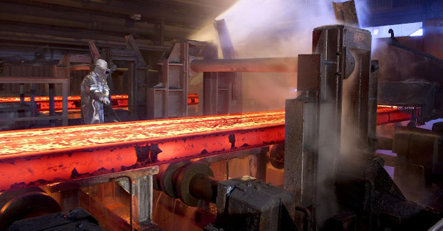
The shearing machine for rolled pieces in transverse shearing operation is called flying shear. It is a processing equipment which can cut off iron plate, steel pipe and paper roll quickly. It is a fixed-size shearing machine for metallurgical steel rolling industry, high-speed wire and threaded steel. It is a product of modern rolling bar shearing and has the characteristics of low power consumption and low investment cost.

Flying shear is an important equipment used for shearing metal billets in iron and steel enterprises, and its performance will directly affect the production efficiency of rolling production line. There are many structural forms of flying shear mechanism. In this chapter, four-link structure is used. Through simple three-dimensional modeling of the frame, upper and lower cranks, upper and lower links, upper and lower rockers and workpieces, assembly and simulation can be carried out to obtain the shear force that the workpiece is subjected to during the shearing process and the motion track of the two cutting edges.

Flying shear is installed on the rolling mill line to cross-cut the head and tail of a rolled piece or to cut it to a fixed length. During the movement of the rolled piece, the rolled piece is cut by relative movements of the cutting edges.

The mechanism sketch of the four-link flying shear mechanism is shown in Figure 1. It consists of the upper and lower shear mechanisms with the cutting edges fixed on the connecting rods of the four-link mechanism. In practical flying shear mechanisms, the driving force is input from the lower crank. The upper crank is driven to move at the same speed by a pair of helical gears with the same number of teeth. Every revolution of the crank, the mechanism shears the work-piece once. In order to simplify the structure and facilitate the measurement of shear force, the same amount of torque is added to both cranks in Figure 1 during simulation to reduce the modeling of helical gears.

Flying shear is commonly used in steel rolling, paper and other production lines. In continuous billet or small section workshops, it is positioned at the back of the rolling mill line, cutting the rolled pieces to size or only to the head and tail. Various types of flying shears are provided in the shearing, shearing, galvanizing and tin plating units of cold and tropical steel workshops to cut the strip into fixed-scale or steel coils of specified weight. The wide use of flying shear is conducive to the rapid development of high-speed and continuous steel rolling production. Therefore, it is one of the important links in the development of steel rolling production.


Please contact stella@hanrm.com for a quotation.
And free send inquiry to us.
Email: stella@hanrm.com   stellarollingmill@gmail.com
Whatsapp/Wechat:+8615877652925
Flying Shears


Hot Rolling Process

Hot Rolling Process

Hot Rolling Process


The semi-finished billet from the steel plant is rolled to make it a qualified product.

Introduction of hot polling process

Process Flow of Hot Rolling: Process Flow of Main Rolling Mill Line:

The slab is directly sent to the slab warehouse of the hot rolling workshop from the slab discharging roller table of the continuous caster in the steelmaking and continuous casting workshop, and the directly hot charged slab is sent to the furnace loading roller table of the reheating furnace for heating. 

The slab that cannot be directly hot charged is lifted into the insulation pit by the crane, and then lifted to the upper material bench by the crane after insulation, and then heated by the furnace loading roller table of the heating furnace, leaving the possibility of direct rolling. 

The continuous casting slab is transported into the slab warehouse by the continuous casting workshop through the slab loading roller table or slab unloading roller table. 

Before the slab reaches the entry point, the technical data about the slab has been sent to the computer system of the hot rolling plant by the computer system of the continuous casting workshop, and the relevant data of the slab is displayed on the monitor, so that the staff can check and receive the defect free and qualified slab. 

In addition, the cleaned slab also needs to be checked, accepted and input into the computer. The flow direction of slabs entering the slab warehouse shall be determined by the slab warehouse computer management system according to the rolling plan.


Conventional slab charging and rolling: after the slab enters the slab warehouse, the slab is stacked to the designated stacking position in the slab warehouse by the slab clamp crane according to the unified instruction of the slab warehouse control system. During rolling, according to the rolling plan, the slab is lifted out of the stack one by one by the slab clamp crane, and lifted to the slab loading bench for loading. 

The slab is weighed and checked by the weighing roller table, and then sent to the furnace loading roller table of the heating furnace. After the slab is measured and positioned, it is loaded into the heating furnace by the steel loader for heating. 

Hot charging and rolling of carbon steel insulation pit: after the slab enters the slab warehouse, the slab is stacked to the designated stacking position in the insulation pit by the slab clamp crane according to the unified instruction of the slab warehouse control system. 

During rolling, according to the rolling plan, the slab is taken out of the insulation pit one by one by the slab clamp crane, lifted to the slab loading bench for loading. The slab is weighed and checked by the weighing roller table, and then sent to the furnace loading roller table of the heating furnace. 

After the slab is measured and positioned, it is loaded into the reheating furnace by the steel loader for heating.

Direct hot charging and rolling: when the production plans of continuous casting and hot rolling match, the qualified high-temperature continuous casting slab is transported to the weighing roller table through the charging roller table of the heating furnace. 

After weighing and checking, it enters the charging roller table of the reheating furnace. 

After the slab is measured and positioned in front of the designated reheating furnace, it is loaded into the reheating furnace by the charging machine for heating. 

Some of the directly hot loaded slabs transported through the unloading roller table need to be lifted by a crane once, placed on the loading roller table and directly sent to the reheating furnace area. 

If the steel-making plant can realize the direct hot charging and the slab is transported by the feeding roller table, some crane lifting operations can be reduced. 

After the slab is sent to the heating furnace through the charging roller table of the reheating furnace, it is loaded into the heating furnace by the supporting machine. 

After heating to the set temperature, it is supported by the tapping machine according to the rolling rhythm and placed on the discharging roller table of the reheating furnace.

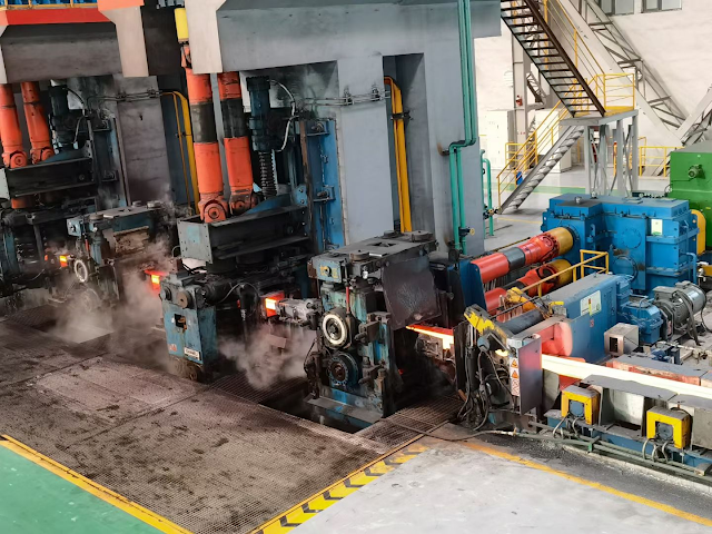
After the heated slab is discharged from the furnace, it is transported through the conveying roller table. After descaling by the high-pressure water descaling device, the slab is sent to the fixed width press for side pressing and fixed width as required. The maximum one-time width reduction of the fixed width press is 350mm. 

Then it is transported by the roller table into the first two high reversible roughing mill and the second four high reversible roughing mill. The slab is rolled into an intermediate slab with a thickness of about 30-60mm according to the process requirements. 

The vertical roll mill in front of each roughing mill can control the width of the intermediate billet. 

An intermediate waste billet pushing device is arranged between R2 and the flying shear to push the intermediate waste billet onto the operation side bench of the intermediate roller table. 

The intermediate billet is transported by the intermediate roller table with thermal insulation cover to the cutting head and tail of the flying shear. The thermal insulation cover is conducive to reducing the heat loss of the intermediate billet and the temperature difference between the head and tail of the belt billet.

An edge heater is set in front of the flying shear, which can reduce the temperature difference between the edge and the middle part of the intermediate billet, improve the uniformity of strip steel performance and improve the quality of rolled piece shape. 

The cutting head flying shear is equipped with an intermediate blank head and tail shape detector and a cutting optimization control system to realize optimal cutting and reduce the loss of cutting head and tail. 

The strip blank after head cutting is removed from the secondary iron oxide scale by the high-pressure water descaling device before finishing rolling, and is guided into the finishing rolling unit by the vertical roll before finishing rolling. 

The intermediate billet is rolled into 1.2 ~ 25.4mm finished strip by F1 ~ F7 four roll finishing mill.

The threading speed, acceleration, maximum rolling speed, reduction of each stand, roll shifting stroke of work roll and roll bending force of each stand of the finishing mill are calculated and set by the computer control system according to the variety and specification of rolled strip to realize the closed-loop control of strip shape. 

In order to effectively control the quality of strip steel, the rolling line detection instruments such as crown, flatness, thickness, width and temperature are set at the outlet of F7 finishing mill, and the rolling line detection instruments such as strip surface quality, width and temperature are set at the inlet of coiler. 

The strip rolled by the finishing mill is cooled from the final rolling temperature to the specified coiling temperature by the strip laminar cooling system on the output roller table. 

The cooling water volume is set and calculated by the computer according to the steel strip cooling mode and final coiling temperature.

When the coiler passes through the strip before biting into the strip, the speed of the output roller table, pinch roll, auxiliary roll and drum is ahead of the rolling speed of the final frame; 

When the strip steel is bitten by the coiler, the output roller table, pinch roll and coiler will conduct speed-up rolling synchronously with the finishing mill; 

When the tail of the strip steel leaves the end frame, the output roller table and pinch roller shall slow down, that is, lag behind the coiling speed of the coiler until the tail of the hot rolled coil.

After coiling, the steel coil is lifted out by the coil unloading trolley to the baler for bundling. Then the steel coil is transported backward by the steel coil transportation system. 

After baling, weighing and marking, it is transported to the hot-rolled steel coil finished product warehouse, cold-rolled raw material warehouse and finishing raw material warehouse respectively. 

After the steel is returned to the hot rolling and coiling warehouse for inspection, the raw materials that need to be transported to the hot rolling and coiling warehouse for inspection are sent to the hot rolling and coiling warehouse for inspection, and the finished products are sent to the hot rolling and coiling warehouse for inspection respectively.

The steel coils cooled in the steel coil warehouse shall be sent to the leveling and winding unit, steel plate cross cutting unit, cold rolling workshop or delivered according to the sales plan according to the next processing process requirements. The steel coil is transported and stacked in the way of horizontal coil. 

The transportation system for the steel coil to the steel coil warehouse or cold rolling raw material warehouse adopts the pallet transportation system, and forms a transportation network together with the transportation system of 1780 hot rolling plant, which is uniformly controlled by the computer.

From the slab entering the slab warehouse to the delivery of finished products, the whole process tracks the slab, rolled piece and coil through the rolling line material tracking system and two warehouse management system, so as to realize the automatic production control of computer.


Please contact stella@hanrm.com for a quotation.
And free send inquiry to us.
Email: stella@hanrm.com   stellarollingmill@gmail.com
Whatsapp/Wechat:+8615877652925
Hot Rolling Process


Wednesday, March 2, 2022

Common Problems and Solutions of Laying Head in High-speed Wire Rod Rolling Mill Producing Process

laying head


Common Problems and Solutions of Laying Head in High-speed Wire Rod Rolling Mill Producing Process


1. Laying Head Tail Flicking

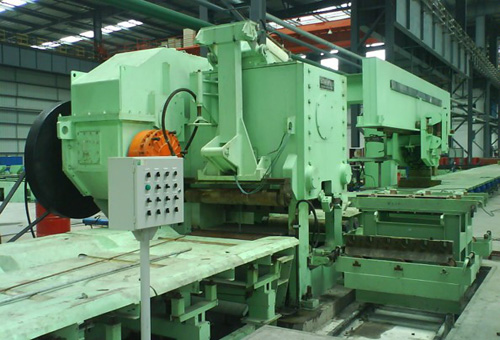
Laying head tail flicking refers to the phenomenon that the tail of the wire rod can not spit out smoothly from the laying head tube and collide with the laying head disk with high-speed rotation. 

The reason is that the tail of the wire rod coil does not have enough speed and force to make the tail of the coil throw out smoothly from the laying head tube. The solution is to prolong the clamping time at the tail of the pinch roll and appropriately improve the clamping speed. 

Another is to change the throwing angle of the outlet section of the laying head tube to reduce the resistance during throwing, so that the tail of the coil can be thrown smoothly.

2. Laying Head Spit Large and Small Circles

spit large and small circles refers to the different diameters of the coils spit out by the wire rod mill laying head, which is mainly due to the unstable tension between the pinch roll and the wire rod mill laying head. 

The solution should start from two aspects: First, maintain the stable clamping of pinch roll. When the clamping state is poor, the speed of the pinch roll is not constant. Second, the laying head pipe may wear out a deep track and should be replaced in time.


3. The Wire Rod Coil of Wire Rod Mill Laying Head is Oval

When producing small-size wire rod and the spinning temperature is too high, it is easy to appear circle oval phenomenon, because the wire rod is relatively soft. 

In addition, when the height of the air-cooled roller table is too low and the falling distance of the coil discharged by the spinning machine is too large, it is also easy to appear elliptical. 

At this time, the turning plate at the outlet of the laying head can be adjusted and its inclination angle can be appropriately reduced. The coil discharged by the wire rod laying head falls on the turning plate slowly first, and then on the roller table. 

In this way, it can ensure that the wire rod coil shape falls evenly in the center of the roller table, and it is not easy to produce an elliptical ring shape.


Please contact stella@hanrm.com for a quotation.
And free send inquiry to us.
Email: stella@hanrm.com   stellarollingmill@gmail.com
Whatsapp/Wechat:+8615877652925

Wire Rod Mill Laying Head


Featured Post

Bar & Wire Rod Rolling Mill Production Line Process Flow (Complete Version)

Bar & Wire Rod Rolling Mill Production Line Process Flow (Complete Version) 1. Bar Rolling Mill Production Line Process Flow  Billet acc...

Popular Articles

My Blog List

Wikipedia

Search results