Showing posts with label crank type flying shear. Show all posts

Tuesday, March 8, 2022

What are Flying Shears?

Flying Shears

What are Flying Shears?

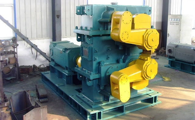
The shearing machine for rolled pieces in transverse shearing operation is called flying shear. It is a processing equipment which can cut off iron plate, steel pipe and paper roll quickly. It is a fixed-size shearing machine for metallurgical steel rolling industry, high-speed wire and threaded steel. It is a product of modern rolling bar shearing and has the characteristics of low power consumption and low investment cost.

Flying shear is an important equipment used for shearing metal billets in iron and steel enterprises, and its performance will directly affect the production efficiency of rolling production line. There are many structural forms of flying shear mechanism. In this chapter, four-link structure is used. Through simple three-dimensional modeling of the frame, upper and lower cranks, upper and lower links, upper and lower rockers and workpieces, assembly and simulation can be carried out to obtain the shear force that the workpiece is subjected to during the shearing process and the motion track of the two cutting edges.

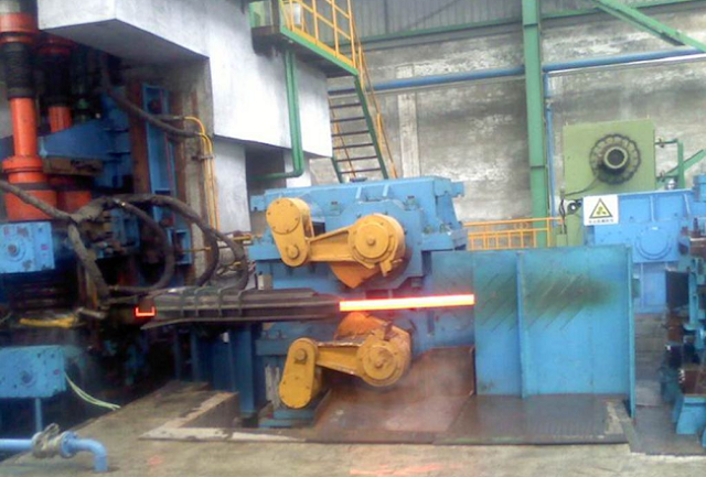
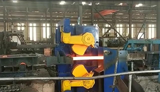
Flying shear is installed on the rolling mill line to cross-cut the head and tail of a rolled piece or to cut it to a fixed length. During the movement of the rolled piece, the rolled piece is cut by relative movements of the cutting edges.

The mechanism sketch of the four-link flying shear mechanism is shown in Figure 1. It consists of the upper and lower shear mechanisms with the cutting edges fixed on the connecting rods of the four-link mechanism. In practical flying shear mechanisms, the driving force is input from the lower crank. The upper crank is driven to move at the same speed by a pair of helical gears with the same number of teeth. Every revolution of the crank, the mechanism shears the work-piece once. In order to simplify the structure and facilitate the measurement of shear force, the same amount of torque is added to both cranks in Figure 1 during simulation to reduce the modeling of helical gears.

Flying shear is commonly used in steel rolling, paper and other production lines. In continuous billet or small section workshops, it is positioned at the back of the rolling mill line, cutting the rolled pieces to size or only to the head and tail. Various types of flying shears are provided in the shearing, shearing, galvanizing and tin plating units of cold and tropical steel workshops to cut the strip into fixed-scale or steel coils of specified weight. The wide use of flying shear is conducive to the rapid development of high-speed and continuous steel rolling production. Therefore, it is one of the important links in the development of steel rolling production.


Please contact stella@hanrm.com for a quotation.
And free send inquiry to us.
Email: stella@hanrm.com   stellarollingmill@gmail.com
Whatsapp/Wechat:+8615877652925

Flying Shears


Saturday, May 8, 2021

Flying Shear in Rolling Mill

Flying Shear


Flying Shear in Rolling Mill


Application and Classification of Flying Shear


The flying shears used to shear the rolling pieces in transverse motion are called rolling mill flying shears. With the development of continuous plate mill, section mill, and billet mill and the improvement of flying shear productivity, the application of flying shear is more and more widely. There are many types of flying shears, such as disc flying shears, double drum flying shears, crank rotary flying shears, and pendulum flying shears.


1. Disc Flying Shear

This kind of flying shear is generally used in the small rolling locomotive room. It is installed in front of the cooling bed to roughly cut the rolled piece, so that the rolled piece entering the cooling bed is not too long; Or it can be installed before the finishing mill to cut the ends of the rolled piece to ensure the smooth-rolling process of the finishing mill. The flying shear consists of two or more pairs of disc-shaped blades. The axis of the disc is equal to the movement speed of the steel. When the flying shear is in the original position, the steel will advance along the inlet duct to the left of the flying shear. When the steel acts on the flag switch or the light guide tube, the inlet tube and the steel incline to the right, and the steel go into the middle of the two discs for shearing. After the lower blade descends, the guide pipe makes the steel return to the original left position, and then the lower blade rises again. The disadvantage of this kind of flying shear is that the cut is inclined, but it has little effect on the cutting or rough cutting of rolled piece before the cooling bed. Because of its reliable operation, simple structure, and shearing speed of more than 10 m / s, it has been widely used in small rolling locomotives.


2. Double Drum Flying Shear

The double drum flying shear is widely used to cut the section steel and steel plate in motion. Its working principle is as follows: two blades are fixed radially on two rotating drums. The rolled piece moving along the roller table is sheared by two blades when passing between two rollers. The circular speed of the blade should be slightly greater than the moving speed of the rolled piece, otherwise, the rolled piece will be bent at the entrance during shearing. The disadvantage of this kind of flying shear is that the section is not smooth when cutting thick rolled pieces (it has too much influence on cutting thin rolled pieces); When the wide steel plate is sheared, the shear force is larger. Therefore, this kind of flying shear is used to shear small section steel and thin plate of high-speed rolling piece.


3. Crank Rotary Flying Shear

Its shearing mechanism is composed of four-bar linkage. The cutting edge moves approximately in-plane in the shearing area and is perpendicular to the surface of the rolled piece. Therefore, the cross-section of the rolled piece is relatively straight. The cutting mechanism of flying shear is composed of tool holder, eccentric sleeve and swing bar. One end of the tool holder is fixed on the eccentric sleeve, and the other end is connected with the swing rod. The swing fulcrum of the swing rod is hinged on the column. When the eccentric sleeve (crank) rotates, the tool holder moves in translation, and the blade fixed on the tool holder can be vertical or nearly vertical to the rolled piece. In order to reduce the shear force, the inclined blade can be used to shear the steel plate. The disadvantage of this kind of flying shear is that the structure is complex, the dynamic load characteristic of the cutting mechanism is poor, and the moving speed of the blade can not be too fast. It is generally used to shear thick steel plate or billet.


4. Swing Flying Shear

This kind of flying shear is sometimes used in the cross-cutting unit of continuous steel plate rolling locomotive. The blade of the flying shear also moves in translation, and the quality of the cutting plate is better. The upper tool rest is fixed on the swing frame. The swing frame is supported by the eccentricity of the spindle. There are two pairs of eccentricities on the spindle. The other pair of eccentricities is connected with the lower tool rest through the connecting rod. The lower tool rest can slide in the chute of the swing frame. Because the two pairs of eccentric positions on the spindle are 180 different °, Therefore, when the spindle rotates, the upper carriage will descend with the frame, while the lower carriage will rise to complete the shearing action. However, it can only shear the static rolled piece. In order to shear the moving workpiece, it is necessary to make the swing frame swing back and forth. The lower part of the swing frame is hinged with an eccentric rod, and the eccentric wheel is installed on the rear axle. The rear axle is connected with the main shaft through the pinion, rack, and synchronous disc. When the main shaft rotates, the rack can swing back and forth with the main shaft as the center through the synchronous disc, rack, pinion, and eccentric connecting rod on the rear shaft. At this time, the tool holder moves in translation to realize the shearing work of the pendulum flying shear. The function of shear in the rolling mill is not the key position, but it plays an important role in the precision and shape of the finished product. Different types of the rolling mills should choose the corresponding flying shear so that the whole production line can achieve the target size and precision.


Free send inquiry to stella@hanrm.com if any needs.
Whatsapp/Wechat:+8615877652925
Website:  https://www.hanrm.com


Rolling mill flying shear

More News You May Interesting:

Why does the Steel Bar Bend after being Cut by Flying Shear?

Finishing Rolling Mill Process Explanation

Reasons and Solutions for the Piling of Wire Rod Rolling

Characteristics and Quality of Wire Rod

Morgan Wire Rod Mill

Headless Welding Rolling Process

Bar Rolling Mills Water Cooling Technology

How to Improve the Thermal Efficiency of the Reheating Furnaces?

Causes of Surface Cracks in High-Speed Wire Rod Rolling Mill

What is Slit Rolling?

Failure Analysis of Cold Mill Roll

Causes and Solution of Steel Piling-up in High-speed Wire Rod Rolling Mills?

Bar Automatic Counting System

Rolling Mill Pass Design


Bar Mill Flying Shear for sale


Thursday, October 10, 2019

Automatic Control Analysis of Bar Continuous Rolling Flying Shear

flying shear


Flying Shear Start Control


Before rolling, the engineer's station personnel passed the screen set to transfer the cut and cut the size of the flying shear to the PLC. When the HMD detects the steelhead or steel tail signal before the shear, the detection signal is sent to the PLC that controls the scissors, and the scissors PLC then according to the line speed of the rolling piece passed by the basic PLC, the last cut of the scissors The error, and the set length of the cutting head and the tail length, calculate the flying shear start delay time. When the delay time is up, the start command of the flying shear is issued immediately, and the cutting function of the flying shear is completed. For the shredding function of the scissors, the manual start control is adopted, and the operation table manually breaks according to the accident. The shredding function of the scissors takes precedence over the function of cutting and cutting.

Rolling Steel Simulation Analysis Function


When the hot test run is not set at the production site, in order to comprehensively evaluate the linkage effect of each device, it can be completed by cold adjustment; when it is judged whether the cascade blocking function is normal, it can be analyzed by the automatic control model; When it is reasonable, it can be operated in a targeted manner, which shortens the trial hot car time to some extent. At the same time, under the action of rolling steel simulation analysis function, online simulation analysis is realized, and through the continuous improvement of offline simulation function, it provides necessary reference information for the development of transmission inverter equipment program. When the PLC is connected correctly, all module performance can be tested in real-time.

bar mill flying shear


Bar Speed Correction


The rolling speed of the bar is the basis for control and the key to controlling the accuracy of the cutting, so the estimation of the speed of the rolled bar is particularly important. When the calibration function is activated, the speed of the bar is corrected. The speed of the rolled material is generally calculated by the mill control system based on the roll diameter, roll profile and motor type, due to elastic strain and rolled material at the stand roll. The actual reduction on the amount, the calculated value may not be consistent with the actual value. The actual speed is estimated by measuring the elapsed time of the end of the bar from the HMD before the flying shear to the time after the HMD. Alternatively, the flying shear performs shearing, and the measurement starts from the interlacing of the blade to the cutting. The time at which the end reaches the HMD downstream of the flying shear. The ratio of the distance between the HMDs and the measured time gives an estimate of the average speed of a bar during operation. A speed calibration factor is obtained relative to the average of the speeds calculated by the mill control system at the same interval. The speed received from the mill control system becomes a speed calibration factor, thereby obtaining the best estimate of the actual speed of the bar during shearing.

Flying shear Zero Compensation Control


After the end of a cutting process, the flying shear must be accurately parked at the zero position to prepare for the next cut. The zero detection of the flying shear is calibrated by the proximity switch. However, in practice, there is a certain error in the stop position from the original zero points. The error must be compensated to ensure that the speed of the scissors is accelerated to the set shear speed within the specified distance to meet the shear torque requirement. For this purpose, the position of the cutting edge is detected using the positioning code dial. The code wheel adopts 2048 two-phase orthogonal pulse. Each rotation of one wheel, the code wheel count is 0-8192, corresponding to the cutting edge angle of 0-360 degrees so that the angle of the scissors from the zero position can be calculated by counting the pulse of the code wheel. By this value and the angle between the zero point and the shear point, the initial angle of the flying shear can be calculated. Since the code wheel can achieve high precision and can effectively suppress the counting error caused by the vibration, the next cutting edge can be accurately compensated for the next cutting edge error.

In summary, the application of the bar shear system, the main technical performance indicators such as shear accuracy, shear section quality, shear response speed and optimized shear reliability can meet the on-site process requirements, in the rolling mill room Under the premise of normal cascading relationship, stable rolling mill speed and normal operation of all detecting components, the absolute value of the positive and negative shear length of the shearing length generally does not exceed the maximum linear velocity (m/s) of the rolling line multiplied by 5 milliseconds. The application of the automation control system has improved the production level to a certain extent, which is an inevitable trend in future development.

flying shear


More News You May Interesting:

Headless Welding Rolling Process

Bar Rolling Mills Water Cooling Technology

How to Improve the Thermal Efficiency of the Reheating Furnaces?

Causes of Surface Cracks in High-Speed Wire Rod Rolling Mill

What is Slit Rolling?

Failure Analysis of Cold Mill Roll

Causes and Solution of Steel Piling-up in High-speed Wire Rod Rolling Mills?

Bar Automatic Counting System

Rolling Mill Pass Design


bar rolling mill flying shear


Featured Post

Bar & Wire Rod Rolling Mill Production Line Process Flow (Complete Version)

Bar & Wire Rod Rolling Mill Production Line Process Flow (Complete Version) 1. Bar Rolling Mill Production Line Process Flow  Billet acc...

Popular Articles

My Blog List

Wikipedia

Search results