Showing posts with label flying shear. Show all posts

Monday, January 16, 2023

The Structure Of Flying Shear

Flying Shear


The Structure Of Flying Shear


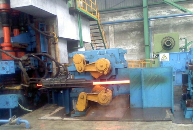
With rolling continuous, high-speed, highly developed degree of automation, flying shear has become a continuous rolling lone indispensable equipment, mainly for hot-rolled and cold-rolled unit length, cutting head, cut tail, cut the sample as well as incident handling, including cold-rolled strip steel drum flying shear, generally arranged before the winding machine, cutting the strip, for sub-volume …. 

As key equipment Rolling Integral continuous production line, support roller bear products at the online clipboard with curly taken to task. Acid rolling mill output of up to 500,000 yuan / h, whether the normal operation of the shears, directly determine whether the normal capacity of the entire line of play. 

A steel rolling mill in 420 acid production early l 998 in the first half, frequently appeared on the shears can not cut the strip normal phenomenon, causing huge economic losses.


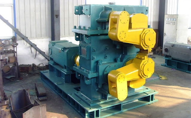
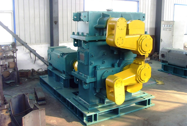
With a flying shear structure, the drum-type mill bearing, generally composed of three parts flying shear body gear and equipment lubrication piping, whose chassis and rotating hub into one, as a whole, not only set up to replace the pair often transfer hub, simple structure rigidity, high cutting precision. 

Flying shear machine body is shown in Figure l, including the transmission mechanism, and cutting mechanism. Flying shear drive mechanism, mainly by the electric motor, gearbox, and synchronous transmission gear mounted on the upper and lower rollers on the drive side of the composition.


Please contact stella@hanrm.com for a quotation.

And free send inquiries to us.

Email: stella@hanrm.com   stellarollingmill@gmail.com

Whatsapp/Wechat:+8615877652925

Thursday, October 10, 2019

Automatic Control Analysis of Bar Continuous Rolling Flying Shear

flying shear


Flying Shear Start Control


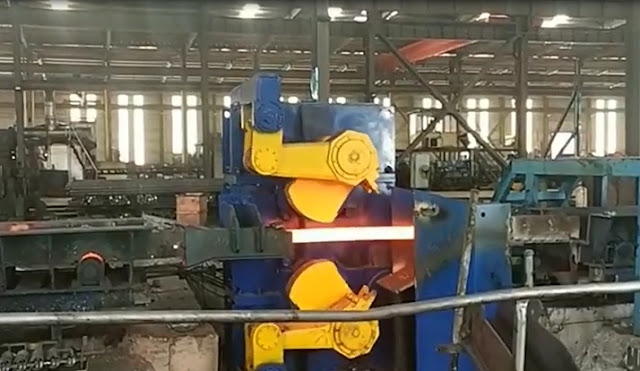
Before rolling, the engineer's station personnel passed the screen set to transfer the cut and cut the size of the flying shear to the PLC. When the HMD detects the steelhead or steel tail signal before the shear, the detection signal is sent to the PLC that controls the scissors, and the scissors PLC then according to the line speed of the rolling piece passed by the basic PLC, the last cut of the scissors The error, and the set length of the cutting head and the tail length, calculate the flying shear start delay time. When the delay time is up, the start command of the flying shear is issued immediately, and the cutting function of the flying shear is completed. For the shredding function of the scissors, the manual start control is adopted, and the operation table manually breaks according to the accident. The shredding function of the scissors takes precedence over the function of cutting and cutting.

Rolling Steel Simulation Analysis Function


When the hot test run is not set at the production site, in order to comprehensively evaluate the linkage effect of each device, it can be completed by cold adjustment; when it is judged whether the cascade blocking function is normal, it can be analyzed by the automatic control model; When it is reasonable, it can be operated in a targeted manner, which shortens the trial hot car time to some extent. At the same time, under the action of rolling steel simulation analysis function, online simulation analysis is realized, and through the continuous improvement of offline simulation function, it provides necessary reference information for the development of transmission inverter equipment program. When the PLC is connected correctly, all module performance can be tested in real-time.

bar mill flying shear


Bar Speed Correction


The rolling speed of the bar is the basis for control and the key to controlling the accuracy of the cutting, so the estimation of the speed of the rolled bar is particularly important. When the calibration function is activated, the speed of the bar is corrected. The speed of the rolled material is generally calculated by the mill control system based on the roll diameter, roll profile and motor type, due to elastic strain and rolled material at the stand roll. The actual reduction on the amount, the calculated value may not be consistent with the actual value. The actual speed is estimated by measuring the elapsed time of the end of the bar from the HMD before the flying shear to the time after the HMD. Alternatively, the flying shear performs shearing, and the measurement starts from the interlacing of the blade to the cutting. The time at which the end reaches the HMD downstream of the flying shear. The ratio of the distance between the HMDs and the measured time gives an estimate of the average speed of a bar during operation. A speed calibration factor is obtained relative to the average of the speeds calculated by the mill control system at the same interval. The speed received from the mill control system becomes a speed calibration factor, thereby obtaining the best estimate of the actual speed of the bar during shearing.

Flying shear Zero Compensation Control


After the end of a cutting process, the flying shear must be accurately parked at the zero position to prepare for the next cut. The zero detection of the flying shear is calibrated by the proximity switch. However, in practice, there is a certain error in the stop position from the original zero points. The error must be compensated to ensure that the speed of the scissors is accelerated to the set shear speed within the specified distance to meet the shear torque requirement. For this purpose, the position of the cutting edge is detected using the positioning code dial. The code wheel adopts 2048 two-phase orthogonal pulse. Each rotation of one wheel, the code wheel count is 0-8192, corresponding to the cutting edge angle of 0-360 degrees so that the angle of the scissors from the zero position can be calculated by counting the pulse of the code wheel. By this value and the angle between the zero point and the shear point, the initial angle of the flying shear can be calculated. Since the code wheel can achieve high precision and can effectively suppress the counting error caused by the vibration, the next cutting edge can be accurately compensated for the next cutting edge error.

In summary, the application of the bar shear system, the main technical performance indicators such as shear accuracy, shear section quality, shear response speed and optimized shear reliability can meet the on-site process requirements, in the rolling mill room Under the premise of normal cascading relationship, stable rolling mill speed and normal operation of all detecting components, the absolute value of the positive and negative shear length of the shearing length generally does not exceed the maximum linear velocity (m/s) of the rolling line multiplied by 5 milliseconds. The application of the automation control system has improved the production level to a certain extent, which is an inevitable trend in future development.

flying shear


More News You May Interesting:

Headless Welding Rolling Process

Bar Rolling Mills Water Cooling Technology

How to Improve the Thermal Efficiency of the Reheating Furnaces?

Causes of Surface Cracks in High-Speed Wire Rod Rolling Mill

What is Slit Rolling?

Failure Analysis of Cold Mill Roll

Causes and Solution of Steel Piling-up in High-speed Wire Rod Rolling Mills?

Bar Automatic Counting System

Rolling Mill Pass Design


bar rolling mill flying shear


Monday, September 30, 2019

What is Wire Rod Mill?

Wire Rod Mill

Wire Rod Mill Brief Introduction


Wire rod mill consists of roughing millintermediate rolling mill, and finishing rolling mill. Roughing mill, intermediate rolling mill and finishing mill are arranged in horizontal, semi-continuous and continuous forms. Continuous finishing mills include horizontal two-roll mill, horizontal-vertical alternating mill, 45-degree non-twist mill, and Y-type mill. A new type of closed roughing and an intermediate rolling mill with the alternating horizontal and vertical arrangement, cantilever non-torsional pre-finishing mill, super heavy top-crossing 45-degree non-torsional finishing mill should be adopted. Non-torsional rolling, tension-free and micro-tension rolling technology should be adopted throughout the line. Start-stop flying shears should be set before rough rolling, medium rolling and finishing rolling to ensure that the rolling speed is not less than 100 m/s and the maximum coil is reached. The single weight is not less than 1.8T. Water cooling devices are installed in front of the finishing mill, between the stands of the finishing mill and behind the finishing mill. Temperature control rolling and cooling control are carried out. Precision rolling is carried out by the sizing and reducing mill, and on-line diameter gauge and flaw detector are equipped. In the production of high-speed wire rod mill, the key equipment of rolling wire into coils for collection is adopted. The speed of the new laying head is over 100 m/s.


The length of roll air-cooled transport line with large air volume delay is not less than 90 M. The direction of the blower and air volume can be adjusted automatically. There are several drops in the air-cooled line for uniform cooling. Walking beam reheating furnace is used as the heating furnace for wire rod mill. It has the functions of automatic steel burning and optimum combustion control. High-pressure water descaling device is installed in front of the rolling mill, and the pressure is not less than 18 MPa. In addition, there are perfect collection and transportation systems, such as automatic volume collection, transportation, bundling, weighing and so on. The main drive motor of wire rod mill is fully digital AC variable frequency speed regulation.


Intermediate Mill

The function of the intermediate mill is to connect the preceding and the following. It can not only produce the finished wire rod with large diameter but also adjust the cross-section size of the rolled piece entering the finishing mill to ensure the stable rolling of the finishing mill. The layout forms of intermediate rolling mills are horizontal, double and continuous, while the continuous layout is divided into two forms: full continuous rolling and semi-continuous rolling. In addition to full continuous rolling, the rolling stock generally forms more than one looper during rolling to facilitate the adjustment. The intermediate mill can be a two-high horizontal mill, a horizontal-vertical alternating arrangement mill, and a Y-type mill. Generally, the length of the looper is controlled by photoelectricity. When the looper is lifted from the lower sleeve, the length of looper can also be controlled by the principle of capacitance or inductance. Flying shears are usually set up between intermediate rolling mill and finishing mill for cutting head and accident shearing.


Roughing Mill


The roughing mill acts as a blanking machine, often using several layout forms, such as horizontal, sequential and continuous. Roughing mills with continuous layout are mostly composed of 6-8 two-roll horizontal mills, which are arranged at the exit of the heating furnace, and twisting rolls are used to turn over steel between the stand. A distributor and a counting device are arranged at the entrance of the roughing mill to realize multi-channel rolling. Flying shears are installed at the exit to remove the splitters that may occur after rolling, to prevent the steel jamming accident when entering the next unit, and to cut the rolling piece continuously when production failure occurs in the next unit. The production of alloy steel or small-batch, multi-variety ordinary steel workshop, sometimes also uses Y-type rolling mill to form a rough rolling unit. At this time, there is no need to twist the steel between the frames, and the blank size used is also flexible, but only can roll a rolled piece.


Finishing Mill


The function of finishing mill is to ensure the production of qualified products. The layout forms are double-double finishing mill, semi-continuous rolling, and full-continuous rolling. Full tandem rolling is divided into the full horizontal mill, horizontal-vertical alternating mill, Y-type finishing mill, and 45-degree finishing mills. There are many double lines finishing mills for wire rod mills in China. They are driven by AC motors in groups and rolled by multi-groove parallel rolling with the enclosure. When rolling, the rolled parts are twisted and tipped. The rolling speed is more than 15-20 m/s and the weight of the disc is less than 160 kg.

The semi-continuous rolling is a two-roll horizontal rolling mill. The rolling operation is carried out in 1~2 trough by parallel operation and twisting steel. The rolling speed is generally about 25~30m/s. Such rolling mills generally use prestressed rolling mills and rolling bearings. The precision of the rolled products is high, the DC motor is used for transmission, and the loops are provided between the racks. Therefore, the adjustment is convenient and the production is flexible. The intermediate frames can be rolled out of different specifications and are suitable for small batches and varieties of wires produce. Horizontal full tandem rolling is a collective transmission, multi-wire rolling, rolling speed is 20-30 m/s; The vertical and horizontal roller mills are arranged alternately by the cantilever type vertical roll and horizontal roll mill. The rolling speed can reach about 35m/s and the weight of the disc can reach 800kg. The rolling speed of Y-type finishing mill can reach 50m/s.


Wire Rod Mill Types and Wire Rod Mill Layout


The production of wire rod is mainly continuous, and the number of rolling mills for the wire rod mill is generally large, which can be divided into roughing rolling, intermediate rolling mill, and finishing mills. Wire rod mill has gone through the development process from horizontal, semi-continuous, continuous to the high-speed rolling mill. Every new type of mill and every new production line arrangement has improved the rolling speed, rolling quality and caries weight of wire rod. High-speed non-twist finishing mill and controlled cooling equipment are used in wire rod production, marking the salivation of a new generation of wire rod mill. The following figure is a sketch of the layout of a Morgan type high-speed wire rod mill in a foreign factory.


The reheating furnace is a roller side-loading side-out walking beam type reheating furnace. The whole wire rod mill line consists of 6 roughing mills, 8 intermediate rolling mills, 4 pre-finishing mills, 8 finishing mills and 4 reducing and sizing mills. The small extension precision rolling is realized. The roughing millintermediate mill, and pre-finishing mill stands are arranged in a flat-upright arrangement, which is a double fulcrum, a long roll body, and a porous compact frame, and the rolling mill is a lower drive. The pre-finishing mill is a compact cantilever roll-ring stand with the alternating horizontal and vertical arrangement. Tungsten carbide roll-ring and roll gap are symmetrically adjusted by the eccentric sleeve. Finishing mill and reducing and sizing mill are top-crossing 45 degree super heavy non-twisting mill. Micro tension or looper control is used between the rolling mill racks.


Featured Post

Bar & Wire Rod Rolling Mill Production Line Process Flow (Complete Version)

Bar & Wire Rod Rolling Mill Production Line Process Flow (Complete Version) 1. Bar Rolling Mill Production Line Process Flow  Billet acc...

Popular Articles

My Blog List

Wikipedia

Search results