Showing posts with label #monoblock mill. Show all posts

Wednesday, May 6, 2020

SMS No-twist Wire Rod Mill

SMS No-twist Wire Rod Mill

SMS No-twist Wire Rod Mill


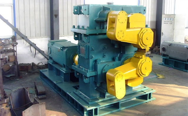
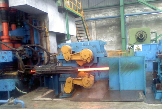
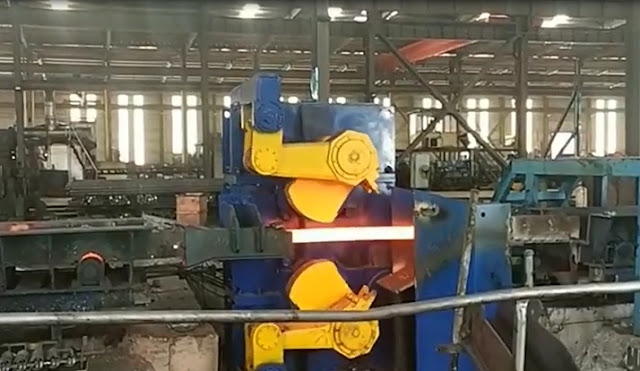
SMS designed a set of rocker arm type high-speed wire rod mill with adjustable roll gap. There are two types of rolling mills layout. One is similar to Morgan type wire rod mill. The adjacent frames are arranged at 90 degrees and 45 degrees alternately with the horizontal plane. The other is that the adjacent frames are still arranged at 90 degrees, but the other is that the adjacent frames are still arranged at 90 degrees with each other. They are at 15/75 degrees above and below the horizontal plane.

According to rolling different steel grades, SMS Group developed three kinds of wire rod finishing mills:


  • High-pressure reduction finishing mill for common steel grades with elongation of 14.5%.
  • The elongation of the finishing mill for high-quality steel grades reaches 9.54%.
  • The elongation of high-grade alloy steel can reach 6.93% in the finishing mill.


The three types of finishing mills have the same basic design, but the reduction rate of each stand is different. So the speed distribution is different. The low reduction rate is used for rolling high deformation resistance steel, while a very high reduction rate can be used for finishing mill when rolling common carbon steel. SMS finishing mill can roll threaded steel bars with diameters of 5.5-16 mm and 6-14 mm, in addition to wire rods with diameters of 5.5-16 mm. The unit has the following characteristics:

The structure of all stand of wire rod finishing mill is the same, so it can be interchanged, and the spare stand can be reduced, which reduces the investment accordingly.

The diameter of the roll ring is standard 210mm. Compared with other roll rings with smaller diameter, it can reduce the rotational speed of the driving system and improve the service life of the rolling groove.

With hydraulic quick clamping and loosening device, the roll ring part can be quickly changed, which can ensure the high productivity of the finishing mill.

The roll shaft installed in the rocker arm can adjust the roll gap symmetrically in a wide range, so as to keep the rolling line constant, which is very advantageous for stabilizing the rolling process, reducing production accidents, and improving the mill operation rate.

The rocker arm mechanism is used to increase the cross-section coefficient of the roller bearing, improve the stiffness and strength of the rolling mill, thus improving the precision of the product and the rolling force of the finishing mill.

The driving system does not use a coupling to prevent vibration.

Compared with the standard roll ring, the life of the tungsten carbide roll ring groove is increased from 400 tons/mm diameter to 900-1000 tons/mm diameter, and the time interval of roll ring replacement is greatly increased.


Please contact stella@hanrm.com for a quotation.
And free send inquiry to us.
Whatsapp/Wechat:+8615877652925

wire rod mill


More News You May Interesting:

Finishing Rolling Mill Process Explanation

Reasons and Solutions for the Piling of Wire Rod Rolling

Characteristics and Quality of Wire Rod

Morgan Wire Rod Mill

Why does the Steel Bar Bend after being Cut by Flying Shear?

Headless Welding Rolling Process

Bar Rolling Mills Water Cooling Technology

How to Improve the Thermal Efficiency of the Reheating Furnaces?

Causes of Surface Cracks in High-Speed Wire Rod Rolling Mill

What is Slit Rolling?

Failure Analysis of Cold Mill Roll

Causes and Solution of Steel Piling-up in High-speed Wire Rod Rolling Mills?

Bar Automatic Counting System

Rolling Mill Pass Design

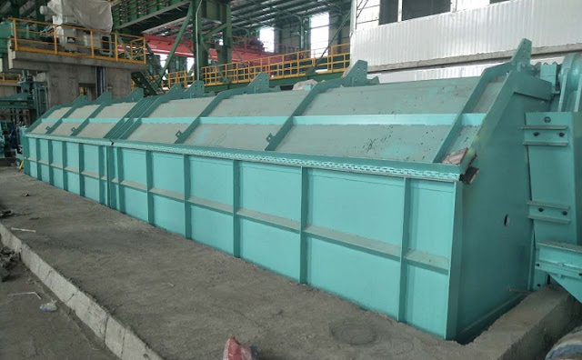
wire rod mill water cooling box


Thursday, October 10, 2019

Automatic Control Analysis of Bar Continuous Rolling Flying Shear

flying shear


Flying Shear Start Control


Before rolling, the engineer's station personnel passed the screen set to transfer the cut and cut the size of the flying shear to the PLC. When the HMD detects the steelhead or steel tail signal before the shear, the detection signal is sent to the PLC that controls the scissors, and the scissors PLC then according to the line speed of the rolling piece passed by the basic PLC, the last cut of the scissors The error, and the set length of the cutting head and the tail length, calculate the flying shear start delay time. When the delay time is up, the start command of the flying shear is issued immediately, and the cutting function of the flying shear is completed. For the shredding function of the scissors, the manual start control is adopted, and the operation table manually breaks according to the accident. The shredding function of the scissors takes precedence over the function of cutting and cutting.

Rolling Steel Simulation Analysis Function


When the hot test run is not set at the production site, in order to comprehensively evaluate the linkage effect of each device, it can be completed by cold adjustment; when it is judged whether the cascade blocking function is normal, it can be analyzed by the automatic control model; When it is reasonable, it can be operated in a targeted manner, which shortens the trial hot car time to some extent. At the same time, under the action of rolling steel simulation analysis function, online simulation analysis is realized, and through the continuous improvement of offline simulation function, it provides necessary reference information for the development of transmission inverter equipment program. When the PLC is connected correctly, all module performance can be tested in real-time.

bar mill flying shear


Bar Speed Correction


The rolling speed of the bar is the basis for control and the key to controlling the accuracy of the cutting, so the estimation of the speed of the rolled bar is particularly important. When the calibration function is activated, the speed of the bar is corrected. The speed of the rolled material is generally calculated by the mill control system based on the roll diameter, roll profile and motor type, due to elastic strain and rolled material at the stand roll. The actual reduction on the amount, the calculated value may not be consistent with the actual value. The actual speed is estimated by measuring the elapsed time of the end of the bar from the HMD before the flying shear to the time after the HMD. Alternatively, the flying shear performs shearing, and the measurement starts from the interlacing of the blade to the cutting. The time at which the end reaches the HMD downstream of the flying shear. The ratio of the distance between the HMDs and the measured time gives an estimate of the average speed of a bar during operation. A speed calibration factor is obtained relative to the average of the speeds calculated by the mill control system at the same interval. The speed received from the mill control system becomes a speed calibration factor, thereby obtaining the best estimate of the actual speed of the bar during shearing.

Flying shear Zero Compensation Control


After the end of a cutting process, the flying shear must be accurately parked at the zero position to prepare for the next cut. The zero detection of the flying shear is calibrated by the proximity switch. However, in practice, there is a certain error in the stop position from the original zero points. The error must be compensated to ensure that the speed of the scissors is accelerated to the set shear speed within the specified distance to meet the shear torque requirement. For this purpose, the position of the cutting edge is detected using the positioning code dial. The code wheel adopts 2048 two-phase orthogonal pulse. Each rotation of one wheel, the code wheel count is 0-8192, corresponding to the cutting edge angle of 0-360 degrees so that the angle of the scissors from the zero position can be calculated by counting the pulse of the code wheel. By this value and the angle between the zero point and the shear point, the initial angle of the flying shear can be calculated. Since the code wheel can achieve high precision and can effectively suppress the counting error caused by the vibration, the next cutting edge can be accurately compensated for the next cutting edge error.

In summary, the application of the bar shear system, the main technical performance indicators such as shear accuracy, shear section quality, shear response speed and optimized shear reliability can meet the on-site process requirements, in the rolling mill room Under the premise of normal cascading relationship, stable rolling mill speed and normal operation of all detecting components, the absolute value of the positive and negative shear length of the shearing length generally does not exceed the maximum linear velocity (m/s) of the rolling line multiplied by 5 milliseconds. The application of the automation control system has improved the production level to a certain extent, which is an inevitable trend in future development.

flying shear


More News You May Interesting:

Headless Welding Rolling Process

Bar Rolling Mills Water Cooling Technology

How to Improve the Thermal Efficiency of the Reheating Furnaces?

Causes of Surface Cracks in High-Speed Wire Rod Rolling Mill

What is Slit Rolling?

Failure Analysis of Cold Mill Roll

Causes and Solution of Steel Piling-up in High-speed Wire Rod Rolling Mills?

Bar Automatic Counting System

Rolling Mill Pass Design


bar rolling mill flying shear


Thursday, August 29, 2019

Continuous Rolling Mill


Continuous Rolling Mill


The main working principle of continuous rolling mill is that when the billet is heated and discharged from the furnace, the oxidized iron sheet is removed by high-pressure water, and then the billet is processed in a four-roll reversible roughing mill. Finally, the intermediate billet which we need and suitable for continuous rolling mill is rolled. In the process of billet opening, the vertical roll can effectively ensure the precise width of the steel plate and the intermediate billet. After shearing, it will directly enter the continuous rolling mill to wait for processing and can be rolled to the specifications required by customers at one time. After rolling, the coiler will take up the coil. In the process of rolling, the roughing and finishing mill needs high-pressure water for secondary dephosphorization.

Introduction of Four-roll Continuous Rolling Mill:

Main Uses: This kind of mill is a one-way and irreversible four-high cold rolling mill. It is mainly used for rolling stainless steel, aluminum, carbon steel, copper and zinc, and other metals.

Main Features and Structures: The main components of this rolling mill are reducer, motor, universal joint shaft, human gearbox, stand, pressing part, electronic control cabinet, and roll system. The roll system uses special bearings for continuous rolling mill. The material of roll is 9Cr2Mo. If it is a large mill bearing base, it will also have a roll changing device.


Friday, July 12, 2019

HOT ROLLING MILL PROJECT


HOT ROLLING MILL PROJECT


2. Production wire rod mill line Summarize

  1) Annual Capacity: Around 30,000tons wire rod mill
  2) Raw material: 100*100*3000mm billet 
  3) Finished products: wire rod ¢5.5--¢12
  4) Steel-types of rollingLow carbon alloy steel, stainless steel, plain  carbon steel

2. Power consumption of total loads for the equipment

     Around 2650kw Approximately

3. Total price for the Turn Key ( Including Furnace, motor, etc. )

      
4. Design process: 

   The Billets feeding into the reheating furnace, and come to the rolling mill, through 3hi rolling mill to 2hi rolling mill, after 22 passes, and become finished products wire rod.

5. All equipment list from Manufacturing Area

1).  Φ350 Rough rolling mill, 3-hi
Scope of supply
Item
Quantity
Note
Φ1800mm flying wheel
1 set
cast steel
Reducer 1pcs
1pcs
cast steel (herringbone tooth)
Three axle box A=350mm
1pcs
cast steel
Cardan joint
3pcs
cast steel
Rack  A=350mm
1set
cast steel
Mill roll
3pcs
70MO2Mn
Bearing pedestal
6set
cast steel
630KW-8 Motor
1pcs
630kw


2). Φ280 Rough rolling mill, 3-hi
Item
Quantity
Note
Motor
1set
540KW
Reducer 1pcs
1set
cast steel (herringbone tooth)
Three axle box A=350mm
1pcs
cast steel
Cardan joint
3pcs
cast steel
Rack  A=280mm3-hi
2set
cast steel
Rack  A=280mm2-hi
1set
cast steel
Mill roll
8pcs
70MO2Mn
Bearing pedestal
16sets  
cast steel

Item
Quantity
Note
Motor
1pcs
280KW
Reducer
1pcs
ZD60
Composite reducer
1pcs

Herringbone tooth 2-axle box
2pcs
A=250
Rack
6pcs
A=250
Cardan joint
12pcs
SWP235type
Mill roll
12pcs
Nodular cast iron
Bearing pedestal
24set


3).  Φ250 one-drive-two rolling mill, 1 set    (K6--K5)              
    
4).  Φ250 one-drive-two rolling mill, 1 set    (K4--K3)  
Item
Quantity
Note
Motor
1pcs
280KW
Reducer
1pcs
ZD60
Composite reducer
1pcs

Herringbone tooth 2-axle box
2pcs
A=250
Rack
6pcs
A=250
Cardan joint
12pcs
SWP235type
Mill roll
12pcs
Nodular cast iron
Bearing pedestal
24set


5).  Φ250 one-drive-two rolling mill, 1 set   (K2--K1)                  
Scope of supply
Item
Quantity
Note
Motor
1pcs
320KW
Reducer
1pcs
ZD60
Composite reducer
1pcs

Herringbone tooth 2-axle box
2pcs
A=250
Rack
6pcs
A=250
Cardan joint
12pcs
SWP235type
Mill roll
12pcs
Nodular cast iron
Bearing pedestal
24set


6. Other equipment

Item
Quantity
Note
Reheating furnace
1set
22m*3.5m
Pushing device
1pcs

form a complete set
Discharge machine
1pcs
Runout roller table
1set
Scattered cold roller
1set
40m
Head cutting shear
1pcs


Form
 A
 complete set
Tail cutting shear
1pcs
Pinch roll
2pcs
Winding machine
1set
Before the roller billet
1set
Lift roller
3set
Transportation Roller
3set
The connection roller
1set

7. Wire Rod Mill Layout:


Featured Post

Bar & Wire Rod Rolling Mill Production Line Process Flow (Complete Version)

Bar & Wire Rod Rolling Mill Production Line Process Flow (Complete Version) 1. Bar Rolling Mill Production Line Process Flow  Billet acc...

Popular Articles

My Blog List

Wikipedia

Search results