Tuesday, March 8, 2022

Hot Rolling Process

Hot Rolling Process

Hot Rolling Process


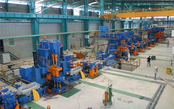
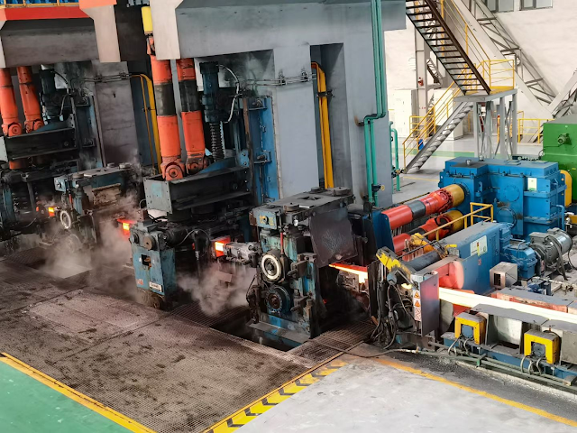
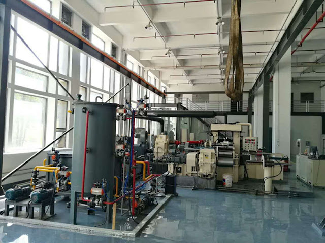
The semi-finished billet from the steel plant is rolled to make it a qualified product.

Introduction of hot polling process

Process Flow of Hot Rolling: Process Flow of Main Rolling Mill Line:

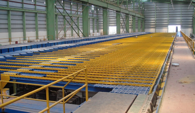
The slab is directly sent to the slab warehouse of the hot rolling workshop from the slab discharging roller table of the continuous caster in the steelmaking and continuous casting workshop, and the directly hot charged slab is sent to the furnace loading roller table of the reheating furnace for heating. 

The slab that cannot be directly hot charged is lifted into the insulation pit by the crane, and then lifted to the upper material bench by the crane after insulation, and then heated by the furnace loading roller table of the heating furnace, leaving the possibility of direct rolling. 

The continuous casting slab is transported into the slab warehouse by the continuous casting workshop through the slab loading roller table or slab unloading roller table. 

Before the slab reaches the entry point, the technical data about the slab has been sent to the computer system of the hot rolling plant by the computer system of the continuous casting workshop, and the relevant data of the slab is displayed on the monitor, so that the staff can check and receive the defect free and qualified slab. 

In addition, the cleaned slab also needs to be checked, accepted and input into the computer. The flow direction of slabs entering the slab warehouse shall be determined by the slab warehouse computer management system according to the rolling plan.


Conventional slab charging and rolling: after the slab enters the slab warehouse, the slab is stacked to the designated stacking position in the slab warehouse by the slab clamp crane according to the unified instruction of the slab warehouse control system. During rolling, according to the rolling plan, the slab is lifted out of the stack one by one by the slab clamp crane, and lifted to the slab loading bench for loading. 

The slab is weighed and checked by the weighing roller table, and then sent to the furnace loading roller table of the heating furnace. After the slab is measured and positioned, it is loaded into the heating furnace by the steel loader for heating. 

Hot charging and rolling of carbon steel insulation pit: after the slab enters the slab warehouse, the slab is stacked to the designated stacking position in the insulation pit by the slab clamp crane according to the unified instruction of the slab warehouse control system. 

During rolling, according to the rolling plan, the slab is taken out of the insulation pit one by one by the slab clamp crane, lifted to the slab loading bench for loading. The slab is weighed and checked by the weighing roller table, and then sent to the furnace loading roller table of the heating furnace. 

After the slab is measured and positioned, it is loaded into the reheating furnace by the steel loader for heating.

Direct hot charging and rolling: when the production plans of continuous casting and hot rolling match, the qualified high-temperature continuous casting slab is transported to the weighing roller table through the charging roller table of the heating furnace. 

After weighing and checking, it enters the charging roller table of the reheating furnace. 

After the slab is measured and positioned in front of the designated reheating furnace, it is loaded into the reheating furnace by the charging machine for heating. 

Some of the directly hot loaded slabs transported through the unloading roller table need to be lifted by a crane once, placed on the loading roller table and directly sent to the reheating furnace area. 

If the steel-making plant can realize the direct hot charging and the slab is transported by the feeding roller table, some crane lifting operations can be reduced. 

After the slab is sent to the heating furnace through the charging roller table of the reheating furnace, it is loaded into the heating furnace by the supporting machine. 

After heating to the set temperature, it is supported by the tapping machine according to the rolling rhythm and placed on the discharging roller table of the reheating furnace.

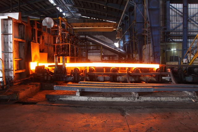
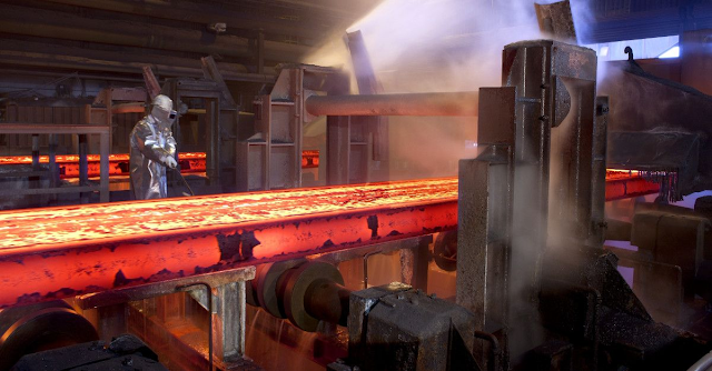
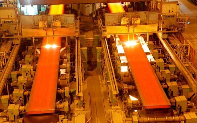
After the heated slab is discharged from the furnace, it is transported through the conveying roller table. After descaling by the high-pressure water descaling device, the slab is sent to the fixed width press for side pressing and fixed width as required. The maximum one-time width reduction of the fixed width press is 350mm. 

Then it is transported by the roller table into the first two high reversible roughing mill and the second four high reversible roughing mill. The slab is rolled into an intermediate slab with a thickness of about 30-60mm according to the process requirements. 

The vertical roll mill in front of each roughing mill can control the width of the intermediate billet. 

An intermediate waste billet pushing device is arranged between R2 and the flying shear to push the intermediate waste billet onto the operation side bench of the intermediate roller table. 

The intermediate billet is transported by the intermediate roller table with thermal insulation cover to the cutting head and tail of the flying shear. The thermal insulation cover is conducive to reducing the heat loss of the intermediate billet and the temperature difference between the head and tail of the belt billet.

An edge heater is set in front of the flying shear, which can reduce the temperature difference between the edge and the middle part of the intermediate billet, improve the uniformity of strip steel performance and improve the quality of rolled piece shape. 

The cutting head flying shear is equipped with an intermediate blank head and tail shape detector and a cutting optimization control system to realize optimal cutting and reduce the loss of cutting head and tail. 

The strip blank after head cutting is removed from the secondary iron oxide scale by the high-pressure water descaling device before finishing rolling, and is guided into the finishing rolling unit by the vertical roll before finishing rolling. 

The intermediate billet is rolled into 1.2 ~ 25.4mm finished strip by F1 ~ F7 four roll finishing mill.

The threading speed, acceleration, maximum rolling speed, reduction of each stand, roll shifting stroke of work roll and roll bending force of each stand of the finishing mill are calculated and set by the computer control system according to the variety and specification of rolled strip to realize the closed-loop control of strip shape. 

In order to effectively control the quality of strip steel, the rolling line detection instruments such as crown, flatness, thickness, width and temperature are set at the outlet of F7 finishing mill, and the rolling line detection instruments such as strip surface quality, width and temperature are set at the inlet of coiler. 

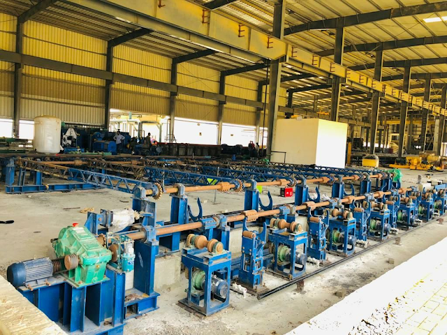
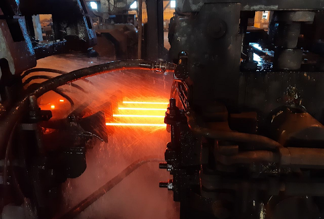
The strip rolled by the finishing mill is cooled from the final rolling temperature to the specified coiling temperature by the strip laminar cooling system on the output roller table. 

The cooling water volume is set and calculated by the computer according to the steel strip cooling mode and final coiling temperature.

When the coiler passes through the strip before biting into the strip, the speed of the output roller table, pinch roll, auxiliary roll and drum is ahead of the rolling speed of the final frame; 

When the strip steel is bitten by the coiler, the output roller table, pinch roll and coiler will conduct speed-up rolling synchronously with the finishing mill; 

When the tail of the strip steel leaves the end frame, the output roller table and pinch roller shall slow down, that is, lag behind the coiling speed of the coiler until the tail of the hot rolled coil.

After coiling, the steel coil is lifted out by the coil unloading trolley to the baler for bundling. Then the steel coil is transported backward by the steel coil transportation system. 

After baling, weighing and marking, it is transported to the hot-rolled steel coil finished product warehouse, cold-rolled raw material warehouse and finishing raw material warehouse respectively. 

After the steel is returned to the hot rolling and coiling warehouse for inspection, the raw materials that need to be transported to the hot rolling and coiling warehouse for inspection are sent to the hot rolling and coiling warehouse for inspection, and the finished products are sent to the hot rolling and coiling warehouse for inspection respectively.

The steel coils cooled in the steel coil warehouse shall be sent to the leveling and winding unit, steel plate cross cutting unit, cold rolling workshop or delivered according to the sales plan according to the next processing process requirements. The steel coil is transported and stacked in the way of horizontal coil. 

The transportation system for the steel coil to the steel coil warehouse or cold rolling raw material warehouse adopts the pallet transportation system, and forms a transportation network together with the transportation system of 1780 hot rolling plant, which is uniformly controlled by the computer.

From the slab entering the slab warehouse to the delivery of finished products, the whole process tracks the slab, rolled piece and coil through the rolling line material tracking system and two warehouse management system, so as to realize the automatic production control of computer.


Please contact stella@hanrm.com for a quotation.
And free send inquiry to us.
Email: stella@hanrm.com   stellarollingmill@gmail.com
Whatsapp/Wechat:+8615877652925

Hot Rolling Process


Wednesday, March 2, 2022

Common Problems and Solutions of Laying Head in High-speed Wire Rod Rolling Mill Producing Process

laying head


Common Problems and Solutions of Laying Head in High-speed Wire Rod Rolling Mill Producing Process


1. Laying Head Tail Flicking

Laying head tail flicking refers to the phenomenon that the tail of the wire rod can not spit out smoothly from the laying head tube and collide with the laying head disk with high-speed rotation. 

The reason is that the tail of the wire rod coil does not have enough speed and force to make the tail of the coil throw out smoothly from the laying head tube. The solution is to prolong the clamping time at the tail of the pinch roll and appropriately improve the clamping speed. 

Another is to change the throwing angle of the outlet section of the laying head tube to reduce the resistance during throwing, so that the tail of the coil can be thrown smoothly.

2. Laying Head Spit Large and Small Circles

spit large and small circles refers to the different diameters of the coils spit out by the wire rod mill laying head, which is mainly due to the unstable tension between the pinch roll and the wire rod mill laying head. 

The solution should start from two aspects: First, maintain the stable clamping of pinch roll. When the clamping state is poor, the speed of the pinch roll is not constant. Second, the laying head pipe may wear out a deep track and should be replaced in time.


3. The Wire Rod Coil of Wire Rod Mill Laying Head is Oval

When producing small-size wire rod and the spinning temperature is too high, it is easy to appear circle oval phenomenon, because the wire rod is relatively soft. 

In addition, when the height of the air-cooled roller table is too low and the falling distance of the coil discharged by the spinning machine is too large, it is also easy to appear elliptical. 

At this time, the turning plate at the outlet of the laying head can be adjusted and its inclination angle can be appropriately reduced. The coil discharged by the wire rod laying head falls on the turning plate slowly first, and then on the roller table. 

In this way, it can ensure that the wire rod coil shape falls evenly in the center of the roller table, and it is not easy to produce an elliptical ring shape.


Please contact stella@hanrm.com for a quotation.
And free send inquiry to us.
Email: stella@hanrm.com   stellarollingmill@gmail.com
Whatsapp/Wechat:+8615877652925


Wire Rod Mill Laying Head


Thursday, February 10, 2022

Low Temperature Rolling Technology of SBQ Special Steel Bar Rolling Mill

Steel Bar Rolling Mill


Low Temperature Rolling Technology of SBQ Special Steel Bar Rolling Mill


1. Preface


The bar rolling mill with the most advanced low temperature rolling (LTR) process built by Hani tech has been running smoothly since it was put into operation in early 2006, and has already reached full capacity, achieving good production performance and application effect. No. 1 SBQ special steel bar rollinhmill RM1 is part of the largest construction project implemented by Hani Tech in China. The project also includes the second set of Danieli "twin" bar mill RM2, which is specially used to produce ordinary steel deformed steel bars. It is arranged in the span adjacent to RM1 and installed and commissioned simultaneously with RM1 mill.

steel bar rolling mill for sale

Danieli has carried out a lot of experimental research to reduce the material hardness of medium and low alloy steels, especially all steel grades that require good shear properties and are prone to cracks due to excessive hardness and stress concentration. For stainless steel production, many experimental studies have also been carried out to improve the mechanical properties of hot rolled materials for some specific purposes. In order to control the performance indexes of materials, such as hardenability and toughness, how to change the grain size and austenite transformation structure of materials has also attracted great attention.


2 . Overview of Steel Plant


The newly built No. 1 SBQ special steel bar mill RM1 (and its "twin" bar mill RM2) is an 18 stand mill with horizontal / vertical arrangement and looper control function. Two water cooling tanks are arranged between No. 14 and No. 15 racks, and a suitable distance is reserved to make the surface temperature of rolled pieces uniform. Due to this arrangement, the whole temperature drop can be controlled within 260 ℃ without affecting the product surface quality (such as local undercooling) and phase transformation. Selecting a cooling tube with high heat exchange coefficient can make the rolled piece obtain uniform cooling in the cross section. The DSC metallographic structure control system controlled by PLC can ensure that the appropriate setting parameters of the water cooling box can be obtained to make the rolled piece cool evenly in the length direction. The inlet and outlet pyrometers are used to monitor the actual temperature of rolled pieces and modify the basic parameter settings in real time when necessary.

Bar Rolling Mill layout

After adopting this advanced technology, the process parameters of the heating furnace can be flexibly adjusted according to the production process needs of different steel grades or due to the long rolling cycle without changing the finish rolling temperature.


3. Product Outline


Hani Tech's SBQ special steel bar rolling mill plant has 160 billets × 160mm square billet, billet weight 2350kg. When conventional rolling is adopted, the maximum production capacity of the rolling mill is 150 t / h; When low temperature rolling is adopted, the production capacity is 100 t / h. Product is ф 16mm~ ф 60mm diameter high-quality round steel bar. The main steel grades and product specifications produced by SBQ special steel bar rolling mill of Hani Tech company.

SQB bar mill

4. Production Process


The Rolling temperature is one of the three basic rolling parameters. It will affect each stage of grain refinement in the whole process of thermal deformation.


Grain refinement and grain growth control are the main means of low temperature rolling process. It can affect the time temperature transition curve (such as the position of CCT curve), change the length of grain boundary and change the nucleation position. In particular, temperature is the most important thermodynamic parameter affecting the whole rolling process 

Low temperature rolling tech

Formula (a) gives the influence law of temperature. It can also explain the role of the previous grain size in the grain growth process; And how all material deformation directly affects the final grain size in the low-temperature rolling process.


Tdrex=K1 × ln(——) × dck2 × eu × ek3

(a)

In the formula, K1, K2 and K3 are constants, and the value depends on the rolled steel.


The grain refinement process can be divided into different stages, although different stages may also occur at the same time. The deformation of the original grain will increase the dislocation density, and the nucleus can be formed at the boundary of the new grain. The disappearance and regeneration of new grain boundaries are closely related to the actual temperature. The formation and growth of new grains is a thermodynamic process. 

bar rolling mill

At different stages, recovery, static recrystallization and dynamic recrystallization will occur, which will affect the flow stress curve. Finally, grain growth shows a trend of minimizing grain boundary energy. The critical temperature determines the boundary between grain refinement conditions and fully recrystallized grain growth structure. With the decrease of carbon content, this effect will become more obvious. For steels such as 16mncr, the microstructure with grain refinement of more than 40% can be easily obtained.


It is very important to maintain the temperature in the whole rolling range. In particular, when the surface temperature of the rolled piece is lower than the critical temperature and the core temperature is still in the high temperature range, it is possible to form a non-uniform final structure, including grain size and phase composition. More vigorous forced cooling in a water tank will likely form a quenching and tempering layer, which will affect the final quality of the material. If the temperature difference between the material surface and the core is too large due to out of control, a non-uniform grain structure will be produced; During the final heat treatment, the mechanical properties of the material exceed the specified range.

hot rolling mill

During the test, 30 billets were rolled for each steel grade, and two different temperature ranges were used. The final cooling under these two steel grades and two different conditions is realized by natural cooling, but after the last stand rolling, two different cooling methods are adopted. Take three samples from each rolled piece. One is used for hardness testing and microstructure evaluation in rolling state; The other two are used for heat treatment test.


The cooling curve of the rolled piece on the rolling mill cooling bed affects the mechanical properties of the final material. Because once the CCT curve is determined according to the chemical composition and grain size of the steel, only the cooling route is fixed; The final organization depends on the intersection with the CCT curve. In this case, there is no need to use a cooling bed cover to delay the phase transition process.


5. Heat Treatment


During the test, especially for 60Si2Mn spring steel, many tests have been carried out to optimize the austenite transformation temperature. The amount of ferrite structure and initial grain size in the rolled material are fully considered in the test. In fact, on the one hand, the ferrite structure is suitable for cold shear without cracks in the shear process; On the other hand, it requires full attention to the austenite before quenching. If the phase structure is not handled properly, it is possible to retain the island ferrite structure after quenching, so as to reduce the mechanical properties of the final material.


The target hardness after 40Cr quenching is determined as 52hrc; The target hardness of 60Si2Mn after quenching is 60HRC. In both cases, the national standard requires oil as the quenching medium. According to the national standard, three samples need to be processed in the heat treatment furnace in the laboratory. After tempering treatment, select air cooling mode to cool the sample to room temperature.

bar rolling mill cooling bed

6. Microstructure Analysis


The microstructure test results of 40Cr show that the material rolled at low temperature by LTR has very uniform ferrite / pearlite structure; The ferrite phase is more than 30%. In hot rolled products, the ferrite phase only appears near the grain boundary in the form of pre eutectic phase.


For 60Si2Mn, a higher finish rolling temperature is selected, in which the ferrite phase is more similar to the eutectic structure. In any case, if LTR low temperature rolling is compared with conventional hot rolling process, obvious difference can be seen. This is not only reflected in the grain size (from grade 9 to grade 8), but also in the distribution of microstructure. Uniform cooling can not only ensure uniform microstructure in the cross section, but also avoid coarse grains.


7. Conclusion


The SBQ special steel bar rolling  mill newly built by Hani tech company has determined the low-temperature rolling process shortly after successfully rolling the first batch of billets, so that users can produce high-quality steel conforming to GB national standards.

The finished bar not only has excellent internal and surface quality, but also achieves high dimensional machining accuracy. For low alloy steel, the low temperature rolling process shows that it can completely change the microstructure of the material within the specified range, so as to improve the mechanical properties and technical indexes of the material. To make good use of this production process, people must clearly understand what it really needs for a specific steel, how to carry out subsequent heat treatment, and what the end use of the product is.


Please contact stella@hanrm.com for a quotation.
And free send inquiry to us.
Email: stella@hanrm.com   stellarollingmill@gmail.com
Whatsapp/Wechat:+8615877652925

steel rolling mill


More News You May Interesting:

Finishing Rolling Mill Process Explanation

Reasons and Solutions for the Piling of Wire Rod Rolling

Characteristics and Quality of Wire Rod

Morgan Wire Rod Mill

Why does the Steel Bar Bend after being Cut by Flying Shear?

Headless Welding Rolling Process

Bar Rolling Mills Water Cooling Technology

How to Improve the Thermal Efficiency of the Reheating Furnaces?

Causes of Surface Cracks in High-Speed Wire Rod Rolling Mill

What is Slit Rolling?

Failure Analysis of Cold Mill Roll

Causes and Solution of Steel Piling-up in High-speed Wire Rod Rolling Mills?

Bar Automatic Counting System

Rolling Mill Pass Design


hot rolling

Sunday, July 25, 2021

Features of Plate Surface Quenching Equipment

Plate Surface Quenching Equipment


Features of Plate Surface Quenching Equipment


1. The control system of the plate surface quenching equipment adopts PLC control, with the fast dynamic response, high-temperature control accuracy, strong programming function, professional customized man-machine interface, and highly user-friendly operation instructions.

2. The monitorable system provides a man-machine interface, real-time display of system working status, and adjustable parameters.

3. The plate quenching furnace is controlled by an intermediate frequency resonant power supply, rectification is fully open, and the power factor is high.

4. The cooling method of the plate surface quenching equipment adopts the advanced and reliable heat pipe self-cooling method, which has high cooling efficiency and reliable operation, which effectively guarantees the normal operation of the plate surface quenching equipment.

5. The plate surface quenching equipment adopts a closed-loop temperature control system, and the American Leitai infrared thermometer and German Siemens S7 form a closed-loop control system.

6. Strict hierarchical management system, medium frequency induction heating equipment has a one-key restoration system.


Please contact stella@hanrm.com for a quotation.
And free send inquiry to us.
Email: stella@hanrm.com   stellarollingmill@gmail.com
Whatsapp/Wechat:+8615877652925

Plate Rolling Mill


More News You May Interesting:

Finishing Rolling Mill Process Explanation

Reasons and Solutions for the Piling of Wire Rod Rolling

Characteristics and Quality of Wire Rod

Morgan Wire Rod Mill

Why does the Steel Bar Bend after being Cut by Flying Shear?

Headless Welding Rolling Process

Bar Rolling Mills Water Cooling Technology

How to Improve the Thermal Efficiency of the Reheating Furnaces?

Causes of Surface Cracks in High-Speed Wire Rod Rolling Mill

What is Slit Rolling?

Failure Analysis of Cold Mill Roll

Causes and Solution of Steel Piling-up in High-speed Wire Rod Rolling Mills?

Bar Automatic Counting System

Rolling Mill Pass Design

Hot rolling


Wednesday, July 7, 2021

Metallurgical Slitting Rolling Technology

Slitting Rolling


Metallurgical Slitting Rolling Technology


Whether the rolled piece can be cut is not only related to the thickness of the connecting part and the relative reduction but also closely related to the pass shape and the size of the slit rolling. In the pass design of the slitting process, the design of pre-cutting and slitting holes is particularly important, followed by the vertical box pass. The pass design of these passes is related to the success of slitting and rolling.

The pre-cut split hole is a transitional pass to ensure the smooth slitting of the split hole. Its purpose is to reduce the unevenness of the split pass, so that the splitting wedge can complete the pressing and positioning of the opposite rolling piece, and accurately distribute the rolling. The cross-sectional area of ​​the piece reduces the burden of cutting the hole as much as possible, thereby improving the stability and uniformity of the cutting. The design should have sufficient reduction, the elongation coefficient should be 1.3 to 1.4, the expansion coefficient should be about 0.6, and the height of the connecting belt should be 0.45-0.48 times the height of the hole.

The slitting hole is basically formed by the connection of a double round pass and a slitting wedge. The function of the slitting pass is that the slitting wedge continues to press down the middle of the pre-slit rolling piece, rolling out the same shape as the pass Rolled pieces, so that the thickness of the connecting strip meets the needs of tearing apart multiple rolling pieces in parallel. In the process of slitting and rolling, due to the effect of the slitting wedge, the limitation of the non-porous side wall on both sides of the rolling piece in the slitting pass, and the rolling piece has a more complex cross-sectional shape, the changes of the rolling piece are as follows: Different from conventional rolling. Its main features are as follows. Severe uneven deformation. The compression deformation at the cutting wedge is often greater than that of other parts.

Splitting deformation is no extension or small extension deformation. When slitting the rolled piece in the slitting hole, the reduction at the bottom of the groove is small, while the reduction at the slitting wedge is larger, and the metal is subjected to the action of the slitting wedge, and the horizontal component force pointing to the widthwise direction is larger. It is a forced widening deformation, so the overall extension is small and the widening is larger.

When multiple roots are divided, the cross-sections of the rolling pieces in the middle and the sides are different, and the width of the rolling pieces on both sides is large and the extension is small; the head and middle dimensions of the rolling piece are also different, and the width of the head and tail is widened. The wedge angle of the slitting hole should be reasonable. If it is too small, it will not cut cleanly or cut. If it is too small, it will cause too much clamping force on the slitting wheel and increase the load of the slitting wheel, generally 60°-65°; The rounded corner of the tip is preferably 1~1.5mm. Too sharp will accelerate the wear of the roll; the thickness of the connecting belt should be close to the gap of the roll, 1-2mm is best; the elongation coefficient is 1.08~1.15, and a certain amount is reserved. Broad room for expansion.


Please contact stella@hanrm.com for a quotation.
And free send inquiry to us.
Email: stella@hanrm.com   stellarollingmill@gmail.com
Whatsapp/Wechat:+8615877652925

Slitting Rolling Technology


More News You May Interesting:

Finishing Rolling Mill Process Explanation

Reasons and Solutions for the Piling of Wire Rod Rolling

Characteristics and Quality of Wire Rod

Morgan Wire Rod Mill

Why does the Steel Bar Bend after being Cut by Flying Shear?

Headless Welding Rolling Process

Bar Rolling Mills Water Cooling Technology

How to Improve the Thermal Efficiency of the Reheating Furnaces?

Causes of Surface Cracks in High-Speed Wire Rod Rolling Mill

What is Slit Rolling?

Failure Analysis of Cold Mill Roll

Causes and Solution of Steel Piling-up in High-speed Wire Rod Rolling Mills?

Bar Automatic Counting System

Rolling Mill Pass Design


slit rolling


Tuesday, June 8, 2021

Used 4 Hi Rolling Mill (393 mm width 4.0 mm-1.2 mm ) thickness for SALE

Used 4 Hi Rolling Mill for sale


Used 4 Hi Rolling Mill (393 mm width 4.0 mm-1.2 mm ) thickness for SALE


4HI ROLLING MILL For Sale
Mill Type 4-High rolling Mill
Original Manufacturer United Engineering
Mill Top Speed 1330 Fpm (405 Mpm)
Strip Tension (Maximum) 5875 Lbs (2670 kG) to top speed
Strip Thickness
Maximum entry 0.160” (4 mm)
Minimum Finish 0.050” (1.2 mm)
Strip Width (Maximum) 15.5” (393 mm)
Coil Data – ID 16” OD 57”
Weight 7000 lbs. (3180 kG)

Mill Data 
Work Rolls 6” (152 mm) diameter x 17” (432 mm) barrel length
BUR’s 26” (660 mm) diameter x 17” (432 mm)Roll Face
Hydraulic Screwdown Retrofitted (1986)
Automatic Gage Control System by I2S
Solid Block Winders, Payoff Stands, Coil Car, Overhead Hold Down Arm
HP Main Mill Drive 500 Hp (373 kW)
Winders (entry and exit) 250 Hp (186 kW)
Oil Filtration System
Spare Rolls, Bearings
Computerized PLC Touch Screen Command Controls


Free send inquiry to stella@hanrm.com if any needs.
Whatsapp/Wechat:+8615877652925

4 Hi Rolling Mill


Cold Rolling Mill


Saturday, May 8, 2021

Flying Shear in Rolling Mill

Flying Shear


Flying Shear in Rolling Mill


Application and Classification of Flying Shear


The flying shears used to shear the rolling pieces in transverse motion are called rolling mill flying shears. With the development of continuous plate mill, section mill, and billet mill and the improvement of flying shear productivity, the application of flying shear is more and more widely. There are many types of flying shears, such as disc flying shears, double drum flying shears, crank rotary flying shears, and pendulum flying shears.


1. Disc Flying Shear

This kind of flying shear is generally used in the small rolling locomotive room. It is installed in front of the cooling bed to roughly cut the rolled piece, so that the rolled piece entering the cooling bed is not too long; Or it can be installed before the finishing mill to cut the ends of the rolled piece to ensure the smooth-rolling process of the finishing mill. The flying shear consists of two or more pairs of disc-shaped blades. The axis of the disc is equal to the movement speed of the steel. When the flying shear is in the original position, the steel will advance along the inlet duct to the left of the flying shear. When the steel acts on the flag switch or the light guide tube, the inlet tube and the steel incline to the right, and the steel go into the middle of the two discs for shearing. After the lower blade descends, the guide pipe makes the steel return to the original left position, and then the lower blade rises again. The disadvantage of this kind of flying shear is that the cut is inclined, but it has little effect on the cutting or rough cutting of rolled piece before the cooling bed. Because of its reliable operation, simple structure, and shearing speed of more than 10 m / s, it has been widely used in small rolling locomotives.


2. Double Drum Flying Shear

The double drum flying shear is widely used to cut the section steel and steel plate in motion. Its working principle is as follows: two blades are fixed radially on two rotating drums. The rolled piece moving along the roller table is sheared by two blades when passing between two rollers. The circular speed of the blade should be slightly greater than the moving speed of the rolled piece, otherwise, the rolled piece will be bent at the entrance during shearing. The disadvantage of this kind of flying shear is that the section is not smooth when cutting thick rolled pieces (it has too much influence on cutting thin rolled pieces); When the wide steel plate is sheared, the shear force is larger. Therefore, this kind of flying shear is used to shear small section steel and thin plate of high-speed rolling piece.


3. Crank Rotary Flying Shear

Its shearing mechanism is composed of four-bar linkage. The cutting edge moves approximately in-plane in the shearing area and is perpendicular to the surface of the rolled piece. Therefore, the cross-section of the rolled piece is relatively straight. The cutting mechanism of flying shear is composed of tool holder, eccentric sleeve and swing bar. One end of the tool holder is fixed on the eccentric sleeve, and the other end is connected with the swing rod. The swing fulcrum of the swing rod is hinged on the column. When the eccentric sleeve (crank) rotates, the tool holder moves in translation, and the blade fixed on the tool holder can be vertical or nearly vertical to the rolled piece. In order to reduce the shear force, the inclined blade can be used to shear the steel plate. The disadvantage of this kind of flying shear is that the structure is complex, the dynamic load characteristic of the cutting mechanism is poor, and the moving speed of the blade can not be too fast. It is generally used to shear thick steel plate or billet.


4. Swing Flying Shear

This kind of flying shear is sometimes used in the cross-cutting unit of continuous steel plate rolling locomotive. The blade of the flying shear also moves in translation, and the quality of the cutting plate is better. The upper tool rest is fixed on the swing frame. The swing frame is supported by the eccentricity of the spindle. There are two pairs of eccentricities on the spindle. The other pair of eccentricities is connected with the lower tool rest through the connecting rod. The lower tool rest can slide in the chute of the swing frame. Because the two pairs of eccentric positions on the spindle are 180 different °, Therefore, when the spindle rotates, the upper carriage will descend with the frame, while the lower carriage will rise to complete the shearing action. However, it can only shear the static rolled piece. In order to shear the moving workpiece, it is necessary to make the swing frame swing back and forth. The lower part of the swing frame is hinged with an eccentric rod, and the eccentric wheel is installed on the rear axle. The rear axle is connected with the main shaft through the pinion, rack, and synchronous disc. When the main shaft rotates, the rack can swing back and forth with the main shaft as the center through the synchronous disc, rack, pinion, and eccentric connecting rod on the rear shaft. At this time, the tool holder moves in translation to realize the shearing work of the pendulum flying shear. The function of shear in the rolling mill is not the key position, but it plays an important role in the precision and shape of the finished product. Different types of the rolling mills should choose the corresponding flying shear so that the whole production line can achieve the target size and precision.


Free send inquiry to stella@hanrm.com if any needs.
Whatsapp/Wechat:+8615877652925
Website:  https://www.hanrm.com


Rolling mill flying shear

More News You May Interesting:

Why does the Steel Bar Bend after being Cut by Flying Shear?

Finishing Rolling Mill Process Explanation

Reasons and Solutions for the Piling of Wire Rod Rolling

Characteristics and Quality of Wire Rod

Morgan Wire Rod Mill

Headless Welding Rolling Process

Bar Rolling Mills Water Cooling Technology

How to Improve the Thermal Efficiency of the Reheating Furnaces?

Causes of Surface Cracks in High-Speed Wire Rod Rolling Mill

What is Slit Rolling?

Failure Analysis of Cold Mill Roll

Causes and Solution of Steel Piling-up in High-speed Wire Rod Rolling Mills?

Bar Automatic Counting System

Rolling Mill Pass Design


Bar Mill Flying Shear for sale


Featured Post

Bar & Wire Rod Rolling Mill Production Line Process Flow (Complete Version)

Bar & Wire Rod Rolling Mill Production Line Process Flow (Complete Version) 1. Bar Rolling Mill Production Line Process Flow  Billet acc...

Popular Articles

My Blog List

Wikipedia

Search results